
Planning Agenda item 5B
195 Dunegrass, Site Plan Review
Planning Commission, Thursday, September 18, 2025
Download these 152 pages, 48.2 MB Whole packet, 190 pages, 63.8 MB
Page 30
Text of page 30
MEMORANDUM City of Saugatuck Planning Commission Memo Date: Request: Address: Parcel: Acreage: Complete: City Staff:
September 12, 2025 Site Plan Review 195 Dunegrass Ridge Dr. 03-57-077-004-01 1.52 Yes Grayson Moore
Meeting Date: Applicant: Project Name:
September 18, 2025 Zahn Builders, Inc. Karpf-Owen Residence
Plan Date: Zoning District: Recommendation: Consultant:
July 8, 2025 PUD/CRC Conditional Approval David M. Jirousek, AICP
Overview The applicant has applied to construct a single-family residential dwelling within a previously approved Planned Unit Development (PUD). The dwelling is proposed to be two stories with a front pool and attached garage. This memo provides a compliance review related to all applicable zoning standards and requirements in accordance with the resolution and the overall PUD plan. Background While it is not common for the Planning Commission to review a site plan for a single-family dwelling, it is required per Resolution No. 150610-A (Resolution Approving a Planned Unit Development for the Property Commonly Known as 631 Perryman). In accordance with the PUD approval, development review is subject to specified PUD modifications and conditions, Conservation, Recreation and Camp District (CRC) requirements, as applicable, and general zoning requirements. Zoning Commentary PUD Requirements: The table below outlines the dimensional requirements for the subject PUD.
102 Butler Street P.O. Box 86 Saugatuck, MI 49453 Phone: 269-857-2603 Website: www.saugatuckcity.com
Page 31
Text of page 31
City of Saugatuck Planning Commission 195 Dunegrass Ridge Drive September 12, 2025 Page 2
Regulation Front Setback Side Setback Rear Setback Maximum Height
Requirement 20 feet (PUD modification) 5 feet (PUD modification) 10 feet (PUD modification) 30 feet* (PUD modification)
Review Comment Complies Complies Complies
Complies. The total height between the top of the driveway and the highest point of the roof appears to be 26’9”, although the application states 27’10’. In either case, it is compliant and Fire Department approval was secured. Maximum Lot Coverage 5% Complies. The 1.52-acre lot is 66,615 square feet, and the building footprint is 3,262 square feet (4.9%). * The PUD plan states that “no building shall have a building height exceeding 30 feet as measured from the highest level fire department vehicle access and the eave of the pitched roof.” The applicant has proposed a flat roof, which was not contemplated in the PUD plan. The height requirement was based on Section D105.1 of the International Fire Code (IFC), which states that flat roof measurements are taken at the “top of parapet walls.” Pool: Section 154.022 (G)(12) prohibits pools in front yards. However, that does not necessarily mean that they cannot be forward of a portion of the dwelling. A front yard is defined in Section 154.005 as “[t]he open space extending the full width of the lot, the depth of which is the minimum horizontal distance between the front lot line and the nearest point of the foundation.” The applicant must confirm that the nearest point of the building’s foundation to the front lot line is less than the nearest point of the pool to the front lot line. Because of the curvilinear front lot line, this measurement is not entirely clear. Site and Vegetation Restoration: Section 154.027 (F)(5-6) of the Zoning Ordinance outlines restoration requirements but does not include a specific replanting requirement. The vegetation assurance plan approved by the Michigan Department of Environment, Great Lakes, and Energy (EGLE) states that 41 trees greater than 3” DBH will be removed. Revegetation efforts will involve planting 82 trees on the east side of the lot. Further, the property will be restored and stabilized with native vegetation along the driveway and surrounding the dwelling. The Planning Commission may require amendments or impose additional conditions. Restoration must take place within 60 days of the normal planting season after the final building inspection. Front Fence/Trash Enclosure: The trash enclosure on sheet A001 is surrounded by a four-foot screening fence. Section 154.143 (E)(5) limits fences in front yards to three feet in height. As such, the enclosure will need to be adjusted in height. Alternatively, it can be covered and considered an accessory structure, which would then not be subject to the four-foot height maximum.
Page 32
Text of page 32
City of Saugatuck Planning Commission 195 Dunegrass Ridge Drive September 12, 2025 Page 3
Other General Zoning Requirements: The proposal complies with other single-family dwelling requirements, including those related to minimum area, driveways, setback encroachments, and parking. Site Plan Standards of Approval Applications: The submittal is sufficiently complete for review in accordance with Section 154.061, however, exterior lighting specifications must be provided. The applicant has provided copies of approvals from EGLE (NREPA and restoration), Allegan County Health Department (septic and SESC), and the Fire Department. Public water connection and engineering approvals remain outstanding. Standards for Formal Site Plan Approval: The following standards for site plan review and approval apply to the project per Section 154.063. Comments related to each standard are provided for the Planning Commission's consideration. A. All elements of the site plan shall be harmoniously and efficiently organized in relation to topography, the size and type of lot, the character of adjoining property and the type and size of the buildings. The site will be so developed as not to impede the normal and orderly development or improvement of surrounding property for uses permitted in this chapter. Comment: The overall development plan blends into the landscape and is consistent with the intended character of the PUD. Development will not impact adjacent and nearby properties. B. The landscape shall be preserved in its natural state, insofar as practical, by removing only those areas of vegetation or making those alterations to the topography which are reasonably necessary to develop the site in accordance with the requirements of this chapter. Comment: The proposed area of disturbance appears to limit the overall impact of site work. Alterations to the topography appear to be the minimum necessary to provide the most appropriate building site. The vegetation assurance plan states that 41 trees greater than three inches (DBH) will be removed. Revegetation efforts will involve planting 82 trees on the east side of the lot. Further, the property will be restored and stabilized with native vegetation along the driveway and surrounding the dwelling. C. The site plan shall provide reasonable visual and sound privacy for all dwelling units located therein. Fences, walks, barriers and landscaping shall be used, as appropriate, to accomplish these purposes. Comment: Existing vegetation and hilly topography outside of the limits of disturbance will provide visual screening. No additional screening is recommended. D. All buildings or groups of buildings shall be arranged so as to permit necessary emergency vehicle access as required by the Fire Department.
Page 33
Text of page 33
City of Saugatuck Planning Commission 195 Dunegrass Ridge Drive September 12, 2025 Page 4
Comment: The Fire Department approved the plans on May 7, 2025. E. There shall be provided a pedestrian circulation system which is separated from the vehicular circulation system. In order to ensure public safety, special pedestrian measures, such as crosswalks, crossing signals and other such facilities may be required in the vicinity of schools, playgrounds, local shopping areas and other uses which generate a considerable amount of pedestrian traffic. All federal, state, and local barrier free requirements shall be met. Comment: The PUD plan indicates trails throughout the development. Sidewalks or pathways are not required along the lot frontage. F. The arrangement of public or common ways for vehicular and pedestrian circulation shall be connected to existing or planned streets and pedestrian or bicycle pathways in the area. Streets and drives which are part of an existing or planned street pattern serving adjacent development shall be of a width appropriate to the traffic volume they will carry and shall have a dedicated right-of-way equal to that specified in the City’s land use plan. Comment: The street already exists, and as stated earlier, sidewalks or pathways are not required along the lot frontage. G. All streets shall be developed in accordance with city specifications, unless developed as a private road. Comment: The street has already been constructed. H. Appropriate measures shall be taken to ensure that removal of surface waters will not adversely affect neighboring properties or the public storm drainage system. Provisions shall be made to accommodate storm water, prevent erosion and the formation of dust. The use of detention/retention ponds may be required. Surface water on all paved areas shall be collected at intervals so that it will not obstruct the flow of vehicular or pedestrian traffic, create puddles in paved areas or create erosion problems. Comment: The City’s engineering consultation has stated that the proposed four-foot diameter leach basin is adequate for stormwater from the home. However, due to the steep driveway, additional measures are needed to prevent runoff from the driveway and guest parking area from flowing onto Dunegrass Ridge Drive. Asphalt curbing or similar controls should be installed to direct runoff to at least two additional leach basins, with one potentially replacing the existing catch basin near the road. All engineering comments must be addressed prior to development. I. All loading and unloading areas and outside storage areas, including areas for the storage of trash, which face or are visible from residential districts or public thoroughfares, shall be screened by an opaque wall or landscaped screen not less than six feet in height. (See §§ 154.142 through 154.144).
Page 34
Text of page 34
City of Saugatuck Planning Commission 195 Dunegrass Ridge Drive September 12, 2025 Page 5
Comment: This standard applies to non-residential development. Earlier comments address residential trash bin screening and fence height. J. Exterior lighting shall be arranged so that it is deflected away from adjacent properties and so that it does not impede the vision of traffic along adjacent streets. Flashing or intermittent lights shall not be permitted. Comment: Outdoor light fixture specifications were not provided. K. In approving the site plan, the Planning Commission may recommend that a bond or other financial guarantee of ample sum be furnished by the developer to ensure compliance for such requirements as drives, walks, utilities, parking, landscaping and the like (see § 154.173). Comment: Not applicable. Recommendation We recommend conditional approval based on compliance with the majority of zoning requirements and the satisfaction of most of the site plan review standards. Approval is recommended with the following conditions to ensure compliance with all requirements: 1. 2. 3. 4. 5.
Reduce the front yard trash bin screening fence to three feet in height. Confirm compliance with pool location requirements (no front yard placement). Satisfy all engineering review comments. Secure public water service approval. Provide compliant exterior light fixture specifications.
Page 35
Text of page 35
MEMORANDUM City of Saugatuck Planning Commission Memo Date: Request: Address: Parcel: Acreage: Complete: City Staff:
September 18, 2025 Site Plan Review 195 Dunegrass Ridge Dr. 03-57-077-004-01 1.52 Yes Grayson Moore
Meeting Date: Applicant: Project Name:
September 18, 2025 Zahn Builders, Inc. Karpf-Owen Residence
Plan Date: Zoning District: Recommendation: Consultant:
July 8, 2025 PUD/CRC Conditional Approval David M. Jirousek, AICP
Overview The applicant has applied to construct a single-family residential dwelling within a previously approved Planned Unit Development (PUD). The dwelling is proposed to be two stories with a front pool and attached garage. This memo provides a compliance review related to all applicable zoning standards and requirements in accordance with all applicable resolutions and the overall PUD plan (sheet C-102A). Background The subject lot originally fell within an area designated as “Undeveloped Property” on a site plan associated with a 2013 special land use application, which was approved for eight single-family lots on a portion of the property. The original development was authorized under Resolution No. 131203-A, A Resolution Approving a Special Land Use and Site Plan for the Former Presbyterian Camp Property (i.e., the Barker Application 13-013) to be Developed for SingleFamily Residential Homes and to Attach Reasonable Conditions to Such Development. Under “Conditions and Requirements/Statement of Conditions” within the resolution, it states the following: The Undeveloped Property shall remain undeveloped and no residences or buildings shall be built thereon (with the exception of the improvements specified herein) until and unless the Developer applies for and obtains a formal amendment to both the Approved Site Plan and the special land use approval contained in this Resolution or as part of a 102 Butler Street P.O. Box 86 Saugatuck, MI 49453 Phone: 269-857-2603 Website: www.saugatuckcity.com
Page 36
Text of page 36
City of Saugatuck Planning Commission 195 Dunegrass Ridge Drive September 18, 2025 Page 2
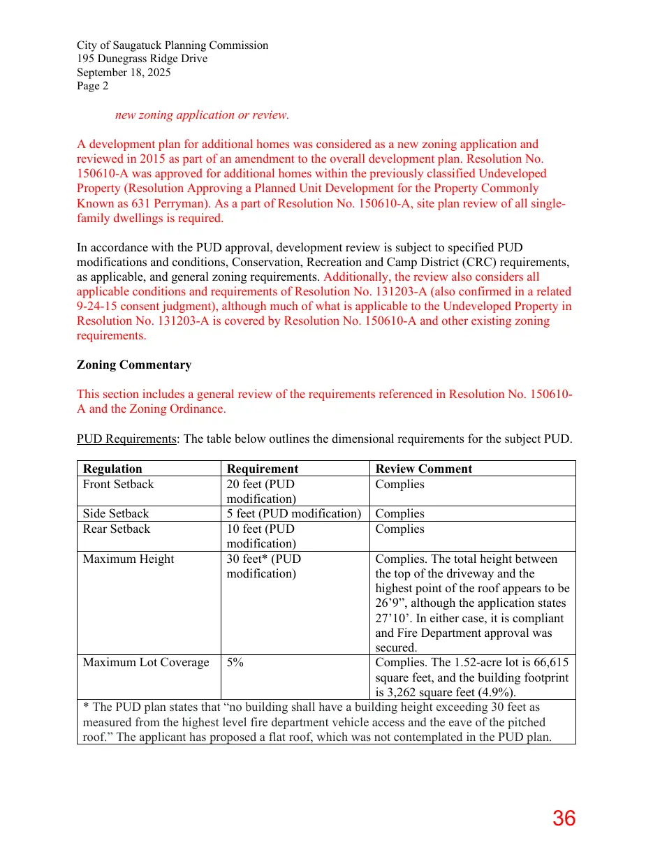
new zoning application or review. A development plan for additional homes was considered as a new zoning application and reviewed in 2015 as part of an amendment to the overall development plan. Resolution No. 150610-A was approved for additional homes within the previously classified Undeveloped Property (Resolution Approving a Planned Unit Development for the Property Commonly Known as 631 Perryman). As a part of Resolution No. 150610-A, site plan review of all singlefamily dwellings is required. In accordance with the PUD approval, development review is subject to specified PUD modifications and conditions, Conservation, Recreation and Camp District (CRC) requirements, as applicable, and general zoning requirements. Additionally, the review also considers all applicable conditions and requirements of Resolution No. 131203-A (also confirmed in a related 9-24-15 consent judgment), although much of what is applicable to the Undeveloped Property in Resolution No. 131203-A is covered by Resolution No. 150610-A and other existing zoning requirements. Zoning Commentary This section includes a general review of the requirements referenced in Resolution No. 150610A and the Zoning Ordinance. PUD Requirements: The table below outlines the dimensional requirements for the subject PUD. Regulation Front Setback Side Setback Rear Setback Maximum Height
Requirement 20 feet (PUD modification) 5 feet (PUD modification) 10 feet (PUD modification) 30 feet* (PUD modification)
Review Comment Complies Complies Complies
Complies. The total height between the top of the driveway and the highest point of the roof appears to be 26’9”, although the application states 27’10’. In either case, it is compliant and Fire Department approval was secured. Maximum Lot Coverage 5% Complies. The 1.52-acre lot is 66,615 square feet, and the building footprint is 3,262 square feet (4.9%). * The PUD plan states that “no building shall have a building height exceeding 30 feet as measured from the highest level fire department vehicle access and the eave of the pitched roof.” The applicant has proposed a flat roof, which was not contemplated in the PUD plan.
Page 37
Text of page 37
City of Saugatuck Planning Commission 195 Dunegrass Ridge Drive September 18, 2025 Page 3
The height requirement was based on Section D105.1 of the International Fire Code (IFC), which states that flat roof measurements are taken at the “top of parapet walls.” Pool: Section 154.022 (G)(12) prohibits pools in front yards. However, that does not necessarily mean that they cannot be forward of a portion of the dwelling. A front yard is defined in Section 154.005 as “[t]he open space extending the full width of the lot, the depth of which is the minimum horizontal distance between the front lot line and the nearest point of the foundation.” The applicant must confirm that the nearest point of the building’s foundation to the front lot line is less than the nearest point of the pool to the front lot line. Because of the curvilinear front lot line, this measurement is not entirely clear. Site and Vegetation Restoration: Resolution No. 150610-A references compliance with Section 154.027 (F)(5-6) of the Zoning Ordinance, which outlines restoration requirements but does not include a specific replanting requirement. The vegetation assurance plan approved by the Michigan Department of Environment, Great Lakes, and Energy (EGLE) states that 41 trees greater than 3” DBH will be removed. Revegetation efforts will involve planting 82 trees on the east side of the lot. Further, the property will be restored and stabilized with native vegetation along the driveway and surrounding the dwelling. The Planning Commission must approve the vegetative removal plan and vegetation assurance plan and may require amendments or impose additional conditions. Restoration must take place within 60 days of the normal planting season after the final building inspection. Front Fence/Trash Enclosure: The trash enclosure on sheet A001 is surrounded by a four-foot screening fence. Section 154.143 (E)(5) limits fences in front yards to three feet in height. As such, the enclosure will need to be adjusted in height. Alternatively, it can be covered and considered an accessory structure, which would then not be subject to the four-foot height maximum. Other General Zoning Requirements: The proposal complies with other single-family dwelling requirements, including those related to minimum area, driveways, setback encroachments, and parking. Resolution No. 131203-A The requirements of Resolution No. 131203-A are primarily related to the “Residential Property” as opposed to the “Undeveloped Property.” Additionally, the resolution acknowledges that no zoning approvals were issued for the Undeveloped Property. However, paragraph e under Conditions and Requirements/Statement of Conditions applies several conditions related to motorized vehicle use, outdoor lighting, vegetation replanting after structure removal, and the removal of trees and other vegetation.
Page 38
Text of page 38
City of Saugatuck Planning Commission 195 Dunegrass Ridge Drive September 18, 2025 Page 4
Resolution No. 150610-A and the Zoning Ordinance cover these issues with more specificity, and no compliance issues with Resolution No. 131203-A are evident. Further, the current site plan also complies with the conditions previously applied to individual lots within the “Residential Property” designated area, which is covered by the special land use approval (outside of the PUD boundary). Most notable is the vegetative removal plan, which is also covered by the Resolution No. 150610-A and Section 154.027 (F)(5-6) of the Zoning Ordinance. Site Plan Standards of Approval Applications: The submittal is sufficiently complete for review in accordance with Section 154.061, however, exterior lighting specifications must be provided. The applicant has provided copies of approvals from EGLE (NREPA and restoration), Allegan County Health Department (septic and SESC), and the Fire Department. Public water connection and engineering approvals remain outstanding. Standards for Formal Site Plan Approval: The following standards for site plan review and approval apply to the project per Section 154.063. Comments related to each standard are provided for the Planning Commission's consideration. A. All elements of the site plan shall be harmoniously and efficiently organized in relation to topography, the size and type of lot, the character of adjoining property and the type and size of the buildings. The site will be so developed as not to impede the normal and orderly development or improvement of surrounding property for uses permitted in this chapter. Comment: The overall development plan blends into the landscape and is consistent with the intended character of the PUD. Development will not impact adjacent and nearby properties. B. The landscape shall be preserved in its natural state, insofar as practical, by removing only those areas of vegetation or making those alterations to the topography which are reasonably necessary to develop the site in accordance with the requirements of this chapter. Comment: The proposed area of disturbance appears to limit the overall impact of site work. Alterations to the topography appear to be the minimum necessary to provide the most appropriate building site. The vegetation assurance plan states that 41 trees greater than three inches (DBH) will be removed. Revegetation efforts will involve planting 82 trees on the east side of the lot. Further, the property will be restored and stabilized with native vegetation along the driveway and surrounding the dwelling. C. The site plan shall provide reasonable visual and sound privacy for all dwelling units located therein. Fences, walks, barriers and landscaping shall be used, as appropriate, to accomplish these purposes. Comment: Existing vegetation and hilly topography outside of the limits of disturbance will provide visual screening. No additional screening is recommended.
Page 39
Text of page 39
City of Saugatuck Planning Commission 195 Dunegrass Ridge Drive September 18, 2025 Page 5
D. All buildings or groups of buildings shall be arranged so as to permit necessary emergency vehicle access as required by the Fire Department. Comment: The Fire Department approved the plans on May 7, 2025. E. There shall be provided a pedestrian circulation system which is separated from the vehicular circulation system. In order to ensure public safety, special pedestrian measures, such as crosswalks, crossing signals and other such facilities may be required in the vicinity of schools, playgrounds, local shopping areas and other uses which generate a considerable amount of pedestrian traffic. All federal, state, and local barrier free requirements shall be met. Comment: The PUD plan indicates trails throughout the development. Sidewalks or pathways are not required along the lot frontage. F. The arrangement of public or common ways for vehicular and pedestrian circulation shall be connected to existing or planned streets and pedestrian or bicycle pathways in the area. Streets and drives which are part of an existing or planned street pattern serving adjacent development shall be of a width appropriate to the traffic volume they will carry and shall have a dedicated right-of-way equal to that specified in the City’s land use plan. Comment: The street already exists, and as stated earlier, sidewalks or pathways are not required along the lot frontage. G. All streets shall be developed in accordance with city specifications, unless developed as a private road. Comment: The street has already been constructed. H. Appropriate measures shall be taken to ensure that removal of surface waters will not adversely affect neighboring properties or the public storm drainage system. Provisions shall be made to accommodate storm water, prevent erosion and the formation of dust. The use of detention/retention ponds may be required. Surface water on all paved areas shall be collected at intervals so that it will not obstruct the flow of vehicular or pedestrian traffic, create puddles in paved areas or create erosion problems. Comment: The City’s engineering consultation has stated that the proposed four-foot diameter leach basin is adequate for stormwater from the home. However, due to the steep driveway, additional measures are needed to prevent runoff from the driveway and guest parking area from flowing onto Dunegrass Ridge Drive. Asphalt curbing or similar controls should be installed to direct runoff to at least two additional leach basins, with one potentially replacing the existing catch basin near the road. All engineering comments must be addressed prior to development.
Page 40
Text of page 40
City of Saugatuck Planning Commission 195 Dunegrass Ridge Drive September 18, 2025 Page 6
I. All loading and unloading areas and outside storage areas, including areas for the storage of trash, which face or are visible from residential districts or public thoroughfares, shall be screened by an opaque wall or landscaped screen not less than six feet in height. (See §§ 154.142 through 154.144). Comment: This standard applies to non-residential development. Earlier comments address residential trash bin screening and fence height. J. Exterior lighting shall be arranged so that it is deflected away from adjacent properties and so that it does not impede the vision of traffic along adjacent streets. Flashing or intermittent lights shall not be permitted. Comment: Outdoor light fixture specifications were not provided. K. In approving the site plan, the Planning Commission may recommend that a bond or other financial guarantee of ample sum be furnished by the developer to ensure compliance for such requirements as drives, walks, utilities, parking, landscaping and the like (see § 154.173). Comment: Not applicable. Recommendation We recommend conditional approval of the site plan, vegetative removal plan, and vegetation assurance plan based on compliance with the majority of zoning requirements and the satisfaction of most of the site plan review standards. Approval is recommended with the following conditions to ensure compliance with the remaining standards and requirements: 1. 2. 3. 4. 5.
Reduce the front yard trash bin screening fence to three feet in height. Confirm compliance with pool location requirements (no front yard placement). Satisfy all engineering review comments. Secure public water service approval. Provide compliant residential exterior light fixture specifications.
Page 41
This page is a scanned image with no text layer. The PDF of these pages has it at full resolution.
Page 42
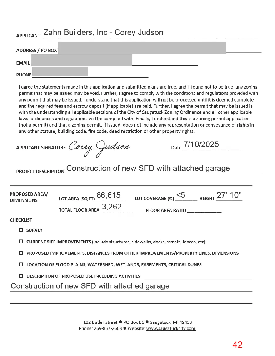
This page is a scanned image with no text layer. The PDF of these pages has it at full resolution.
Page 43
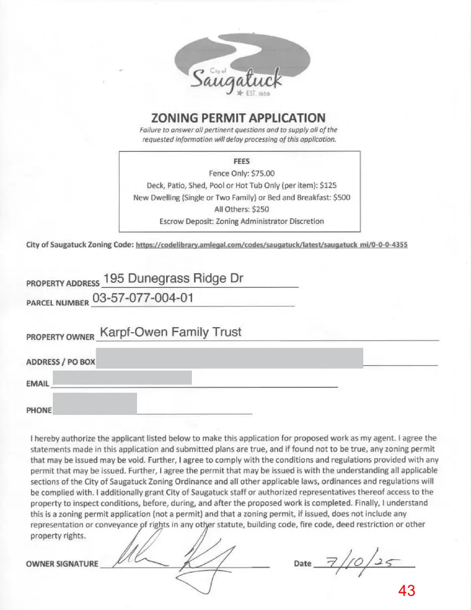
This page is a scanned image with no text layer. The PDF of these pages has it at full resolution.
Page 44
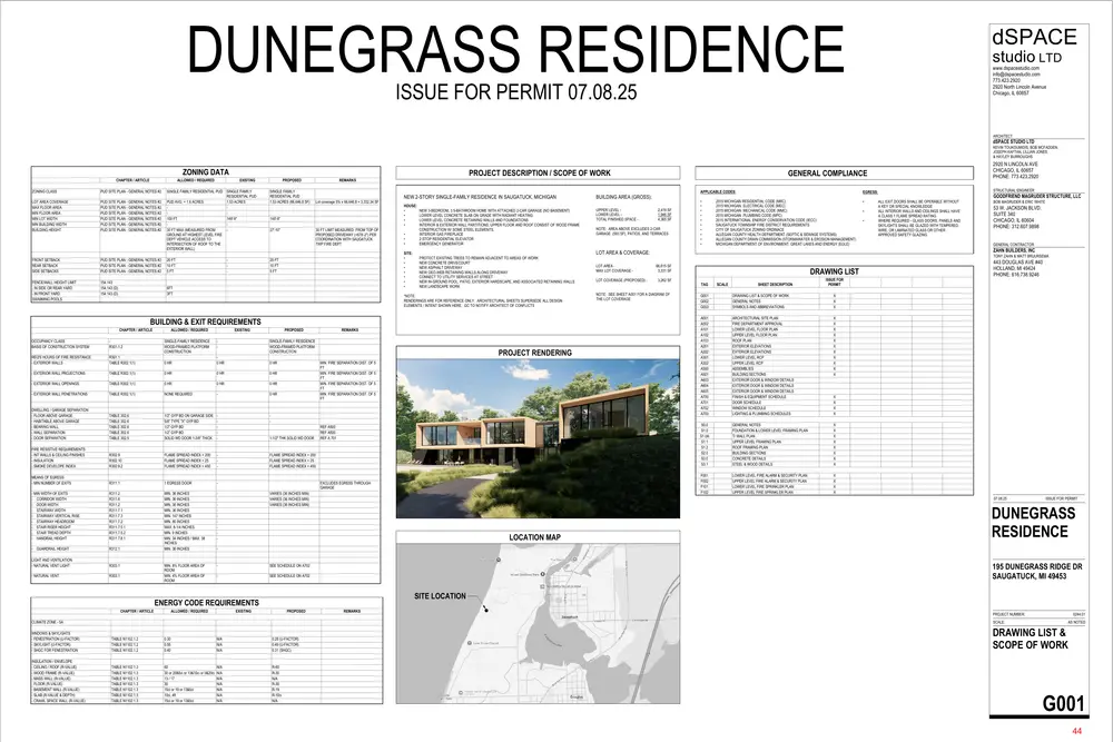
Text of page 44
DUNEGRASS RESIDENCE
dSPACE studio LTD www.dspacestudio.com info@dspacestudio.com 773.423.2920 2920 North Lincoln Avenue Chicago, IL 60657
ISSUE FOR PERMIT 07.08.25
ARCHITECT
dSPACE STUDIO LTD KEVIN TOUKOUMIDIS, BOB MCFADDEN, JOSEPH KAFTAN, LILLIAN JONES, & HAYLEY BURROUGHS
ZONING DATA CHAPTER / ARTICLE
ALLOWED / REQUIRED
ZONING CLASS
PUD SITE PLAN - GENERAL NOTES #2
LOT AREA COVERAGE MAX FLOOR AREA MIN FLOOR AREA MIN LOT WIDTH MIN BUILDING WIDTH BUILDING HEIGHT
PUD SITE PLAN - GENERAL NOTES #2 PUD SITE PLAN - GENERAL NOTES #2 PUD SITE PLAN - GENERAL NOTES #2 PUD SITE PLAN - GENERAL NOTES #2 PUD SITE PLAN - GENERAL NOTES #2 PUD SITE PLAN - GENERAL NOTES #2
FRONT SETBACK REAR SETBACK SIDE SETBACKS
PUD SITE PLAN - GENERAL NOTES #2 PUD SITE PLAN - GENERAL NOTES #2 PUD SITE PLAN - GENERAL NOTES #2
FENCE/WALL HEIGHT LIMIT - IN SIDE OR REAR YARD - IN FRONT YARD SWIMMING POOLS
154.143 154.143 (D) 154.143 (D)
PROJECT DESCRIPTION / SCOPE OF WORK EXISTING
SINGLE FAMILY RESIDENTIAL PUD SINGLE FAMILY RESIDENTIAL PUD PUD AVG. = 1.6 ACRES 1.53 ACRES 100 FT 149'-9" 30 FT MAX (MEASURED FROM GROUND AT HIGHEST LEVEL FIRE DEPT VEHICLE ACCESS TO INTERSECTION OF ROOF TO THE EXTERIOR WALL) 20 FT 10 FT 5 FT
PROPOSED
SINGLE FAMILY RESIDENTIAL PUD 1.53 ACRES (66,646.8 SF)
NEW 2-STORY SINGLE-FAMILY RESIDENCE IN SAUGATUCK, MICHIGAN
30 FT LIMIT MEASURED FROM TOP OF PROPOSED DRIVEWAY (+679'-2") PER COORDINATION WITH SAUGATUCK TWP FIRE DEPT
HOUSE: • NEW 3-BEDROOM, 3.5-BATHROOM HOME WITH ATTACHED 2-CAR GARAGE (NO BASEMENT) • LOWER LEVEL CONCRETE SLAB ON GRADE WITH RADIANT HEATING • LOWER LEVEL CONCRETE RETAINING WALLS AND FOUNDATIONS • INTERIOR & EXTERIOR WALL PARTITIONS, UPPER FLOOR AND ROOF CONSIST OF WOOD FRAME CONSTRUCTION W/ SOME STEEL ELEMENTS. • INTERIOR GAS FIREPLACE • 2-STOP RESIDENTIAL ELEVATOR • EMERGENCY GENERATOR SITE: • • • • • • •
20 FT 10 FT 5 FT
PROTECT EXISTING TREES TO REMAIN ADJACENT TO AREAS OF WORK NEW CONCRETE DRIVECOURT NEW ASPHALT DRIVEWAY NEW GEO-WEB RETAINING WALLS ALONG DRIVEWAY CONNECT TO UTILITY SERVICES AT STREET NEW IN-GROUND POOL, PATIO, EXTERIOR HARDSCAPE, AND ASSOCIATED RETAINING WALLS NEW LANDSCAPE WORK
BUILDING & EXIT REQUIREMENTS OCCUPANCY CLASS BASIS OF CONSTRUCTION SYSTEM
R301.1.2
REQ'S HOURS OF FIRE RESISTANCE - EXTERIOR WALLS
R301.1 TABLE R302.1(1)
- EXTERIOR WALL PROJECTIONS
SINGLE-FAMILY RESIDENCE WOOD-FRAMED PLATFORM CONSTRUCTION
EXISTING
PROPOSED
REMARKS
SINGLE-FAMILY RESIDENCE WOOD-FRAMED PLATFORM CONSTRUCTION
0 HR
0 HR
0 HR
TABLE R302.1(1)
0 HR
0 HR
0 HR
- EXTERIOR WALL OPENINGS
TABLE R302.1(1)
0 HR
0 HR
0 HR
- EXTERIOR WALL PENETRATIONS
TABLE R302.1(1)
NONE REQUIRED
0 HR
DWELLING / GARAGE SEPARATION - FLOOR ABOVE GARAGE - HABITABLE ABOVE GARAGE - BEARING WALL - WALL SEPARATION - DOOR SEPARATION
TABLE 302.6 TABLE 302.6 TABLE 302.6 TABLE 302.6 TABLE 302.5
1/2" GYP BD ON GARAGE SIDE 5/8" TYPE "X" GYP BD 1/2" GYP BD 1/2" GYP BD SOLID WD DOOR 1-3/8" THICK
FIRE RESISTIVE REQUIREMENTS - INT WALLS & CEILING FINISHES - INSULATION - SMOKE DEVELOPE INDEX
R302.9 R302.10 R302.9.2
FLAME SPREAD INDEX < 200 FLAME SPREAD INDEX < 25 FLAME SPREAD INDEX < 450
FLAME SPREAD INDEX < 200 FLAME SPREAD INDEX < 25 FLAME SPREAD INDEX < 450
PROJECT RENDERING MIN. FIRE SEPARATION DIST. OF 5 FT MIN. FIRE SEPARATION DIST. OF 5 FT MIN. FIRE SEPARATION DIST. OF 5 FT MIN. FIRE SEPARATION DIST. OF 5 FT
1-1/2" THK SOLID WD DOOR
MEANS OF EGRESS - MIN NUMBER OF EXITS
R311.1
1 EGRESS DOOR
- MIN WIDTH OF EXITS - CORRIDOR WIDTH - DOOR WIDTH - STAIRWAY WIDTH - STAIRWAY VERTICAL RISE - STAIRWAY HEADROOM - STAIR RISER HEIGHT - STAIR TREAD DEPTH - HANDRAIL HEIGHT
R311.2 R311.6 R311.2 R311.7.1 R311.7.3 R311.7.2 R311.7.5.1 R311.7.5.2 R311.7.8.1
- GUARDRAIL HEIGHT
R312.1
MIN. 36 INCHES MIN. 36 INCHES MIN. 36 INCHES MIN. 36 INCHES MIN. 147 INCHES MIN. 80 INCHES MAX. 8-1/4 INCHES MIN. 9 INCHES MIN. 34 INCHES / MAX. 38 INCHES MIN. 36 INCHES
LIGHT AND VENTILATION - NATURAL VENT LIGHT
R303.1
SEE SCHEDULE ON A702
- NATURAL VENT
R303.1
MIN. 8% FLOOR AREA OF ROOM MIN. 4% FLOOR AREA OF ROOM
SEE SCHEDULE ON A702
REF A500 REF A500 REF A 701
EXCLUDES EGRESS THROUGH GARAGE VARIES (36 INCHES MIN) VARIES (36 INCHES MIN) VARIES (36 INCHES MIN)
2,419 SF 1,946 SF 4,365 SF
NOTE: AREA ABOVE EXCLUDES 2-CAR GARAGE (593 SF), PATIOS, AND TERRACES
EGRESS:
2015 MICHIGAN RESIDENTIAL CODE (MRC) 2015 MICHIGAN ELECTRICAL CODE (MEC) 2015 MICHIGAN MECHANICAL CODE (MMC) 2015 MICHIGAN PLUMBING CODE (MPC) 2015 INTERNATIONAL ENERGY CONSERVATION CODE (IECC) SAUGATUCK TOWNSHIP FIRE DISTRICT REQUIREMENTS CITY OF SAUGATUCK ZONING ORDINACE ALLEGAN COUNTY HEALTH DEPARTMENT (SEPTIC & SEWAGE SYSTEMS) ALLEGAN COUNTY DRAIN COMMISSION (STORMAWATER & EROSION MANAGEMENT) MICHIGAN DEPARTMENT OF ENVIRONMENT, GREAT LAKES AND ENERGY (EGLE)
STRUCTURAL ENGINEER
GOODFRIEND MAGRUDER STRUCTURE, LLC ALL EXIT DOORS SHALL BE OPERABLE WITHOUT A KEY OR SPECIAL KNOWLEDGE ALL INTERIOR WALLS AND CEILINGS SHALL HAVE A CLASS 1 FLAME SPREAD RATING WHERE REQUIRED - GLASS DOORS, PANELS AND SKYLIGHTS SHALL BE GLAZED WITH TEMPERED, WIRE, OR LAMINATED GLASS OR OTHER APPROVED SAFETY GLAZING.
BOB MAGRUDER & ERIC WHITE
53 W. JACKSON BLVD. SUITE 340 CHICAGO, IL 60604 PHONE: 312.607.9898 GENERAL CONTRACTOR
ZAHN BUILDERS, INC TONY ZAHN & MATT BRUURSEMA
LOT AREA MAX LOT COVERAGE -
66,615 SF 3,331 SF
LOT COVERAGE (PROPOSED) -
3,262 SF
DRAWING LIST TAG
NOTE: SEE SHEET A001 FOR A DIAGRAM OF THE LOT COVERAGE
SCALE
SHEET DESCRIPTION
443 DOUGLAS AVE #40 HOLLAND, MI 49424 PHONE: 616.738.9246
ISSUE FOR PERMIT
G001 G002 G003
DRAWING LIST & SCOPE OF WORK GENERAL NOTES SYMBOLS AND ABBREVIATIONS
X X X
A001 A002 A101 A102 A103 A201 A202 A301 A302 A500 A501 A603 A604 A605 A700 A701 A702 A703
ARCHITECTURAL SITE PLAN FIRE DEPARTMENT APPROVAL LOWER LEVEL FLOOR PLAN UPPER LEVEL FLOOR PLAN ROOF PLAN EXTERIOR ELEVATIONS EXTERIOR ELEVATIONS LOWER LEVEL RCP UPPER LEVEL RCP ASSEMBLIES BUILDING SECTIONS EXTERIOR DOOR & WINDOW DETAILS EXTERIOR DOOR & WINDOW DETAILS EXTERIOR DOOR & WINDOW DETAILS FINISH & EQUIPMENT SCHEDULE DOOR SCHEDULE WINDOW SCHEDULE LIGHTING & PLUMBING SCHEDULES
X X X X X X X X X X X
X X X X
S0.0 S1.0 S1.0A S1.1 S1.2 S2.0 S3.0 S3.1
GENERAL NOTES FOUNDATION & LOWER LEVEL FRAMING PLAN T/ WALL PLAN UPPER LEVEL FRAMING PLAN ROOF FRAMING PLAN BUILDING SECTIONS CONCRETE DETAILS STEEL & WOOD DETAILS
X X X X X X X X
F001 F002 F101 F102
LOWER LEVEL FIRE ALARM & SECURITY PLAN UPPER LEVEL FIRE ALARM & SECURITY PLAN LOWER LEVEL FIRE SPRINKLER PLAN UPPER LEVEL FIRE SPRINKLER PLAN
X X X X 07.08.25
LOCATION MAP
ISSUE FOR PERMIT
DUNEGRASS RESIDENCE
195 DUNEGRASS RIDGE DR SAUGATUCK, MI 49453 SITE LOCATION
ENERGY CODE REQUIREMENTS CHAPTER / ARTICLE
UPPER LEVEL LOWER LEVEL TOTAL FINISHED SPACE -
APPLICABLE CODES:
LOT AREA & COVERAGE:
*NOTE: RENDERINGS ARE FOR REFERENCE ONLY. ARCHITECTURAL SHEETS SUPERSEDE ALL DESIGN ELEMENTS / INTENT SHOWN HERE. GC TO NOTIFY ARCHITECT OF CONFLICTS
ALLOWED / REQUIRED
BUILDING AREA (GROSS):
Lot coverage 5% x 66,646.8 = 3,332.34 SF
6FT 3FT
CHAPTER / ARTICLE
GENERAL COMPLIANCE
REMARKS
149'-9" 27'-10"
2920 N LINCOLN AVE CHICAGO, IL 60657 PHONE: 773.423.2920
ALLOWED / REQUIRED
EXISTING
PROPOSED
REMARKS
PROJECT NUMBER: SCALE:
CLIMATE ZONE - 5A WNDOWS & SKYLIGHTS - FENESTRATION (U-FACTOR) - SKYLIGHT (U-FACTOR) - SHGC FOR FENESTRATION
TABLE N1102.1.2 TABLE N1102.1.2 TABLE N1102.1.2
0.30 0.55 0.40
INSULATION / ENVELOPE - CEILING / ROOF (R-VALUE) - WOOD FRAME (R-VALUE) - MASS WALL (R-VALUE) - FLOOR (R-VALUE) - BASEMENT WALL (R-VALUE) - SLAB (R-VALUE & DEPTH) - CRAWL SPACE WALL (R-VALUE)
TABLE N1102.1.3 TABLE N1102.1.3 TABLE N1102.1.3 TABLE N1102.1.3 TABLE N1102.1.3 TABLE N1102.1.3 TABLE N1102.1.3
60 N/A 30 or 20&5ci or 13&10ci or 0&20ci N/A 13 / 17 N/A 30 N/A 15ci or 19 or 13&5ci N/A 10ci, 4ft N/A 15ci or 19 or 13&5ci N/A
N/A N/A N/A
0.28 (U-FACTOR) 0.49 (U-FACTOR) 0.31 (SHGC)
R-60 R-30 N/A R-30 R-19 R-10ci N/A
0244.01 AS NOTED
DRAWING LIST & SCOPE OF WORK
G001 44
Page 45
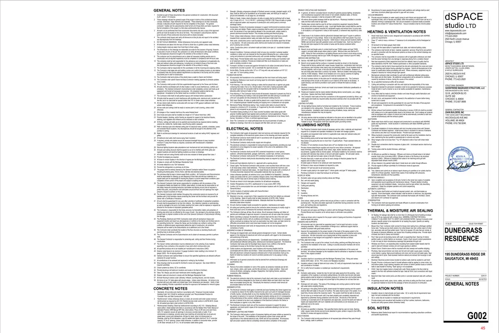
Text of page 45
GENERAL NOTES 1 2
4 5 6 7 8
9 10
11 12
13 14 15 16
17 18 19 20 21 22 23 24 25
26 27 28
29 30 31 32 33 34 35 36 37 38
44 45 46 47 48 49 50 51 52 53 54 55 56 57 58
Included as part of these documents is the general conditions for construction, AIA document A-201, article 1-14 inclusive. These drawings indicate the general scope of the project in terms of the architectural design concept, dimension, major elements and materials. These drawings do not then necessarily indicate or describe all work required for the full completion of the project. The general contractor / builder and his subcontractors shall furnish all of those items and labor required for the full completion of this project in a first-class workmanship-like manner. All work is to be performed from final construction documents only and a copy of the approved permit set must be located on the site at all times. The contractor's subcontractors shall be given full sets of final construction documents with no sheets excluded. The contractor shall inspect and verify all dimensions at the job site and report to the architect any discrepancies from the drawings. DO NOT SCALE DRAWINGS. Written dimensions hold priority over apparent scale. All dimensions are taken from the face of finish to finish face or gridline unless noted otherwise. Ceiling heights noted are taken from finish floor to finish ceiling. The dimensions on the drawings are reasonably accurate for the purpose of figuring; however, in execution of work on the job, the contractor is to verify all dimensions with actual conditions. Any discrepancies should be brought to the attention of the architect in writing. The contractor and his subcontractors are to obtain all necessary building permits prior to construction and all required inspections must be completed in compliance with the local code. The contractor shall be held responsible for the adherence and compliance to all applicable city, state and national codes and ordinances, including but not limited to those of the local code. Any discrepancies should be brought to the attention of the architect in writing. The Contractor shall be responsible for the coordination of all the incoming and outgoing utilities. The Contractor shall stake site and building corners and confirm building location on site relative to propoerty lines and Zoning setback requirements as described in the survey and the contract documents prior to start of construction The Contractor shall send photos of the jobsite twice a week to Owner and Architect. The Contractor shall submit Owner-Architect-Contractor meeting agendas & schedule updates once a week. The Contractor shall provide a full-time superintendent approved by the Owner and Architect. All work shall be coordinated with all other trades in order to avoid interferences, conflicts and omissions. The General Contractor's Subcontractors shall completely connect and hook-up all equipment and furnish all necessary accessories. All completed systems shall be fully operational. Acceptance by the Owner shall be a condition of the contract. The Contractor shall chalk all wall partition layouts with Architect before construction. All studs shall be spaced to avoid interference with plumbing work, electrical work, ductwork and the like, but in no case shall be spaced further than 16" on center unless noted otherwise. All new interior walls shall be constructed with one layer of 5/8" gypsum wallboard, both faces unless noted otherwise. All new walls and ceilings shall be ready to receive paint or wall covering, unless noted otherwise. All changes in floor material shall be at the same finished level. Door knobs and pulls shall be installed at a height of 3'-0" above finish floor, UNO. Provide headers, blocking, and/or framing as required for support of all electrical fixtures, shelving, duct registers and millwork and as indicated on door schedule. All floors, ceilings and walls are to be patched and level/plumb (as required) before installing ceramic tile, marble tile, marble slabs, wood flooring and/or casework. Refer to electrical plan and reflected ceiling plan for electrical notes, symbols, schedules, power, and recessed fixture locations. Any discrepancies should be brought to the attention of the architect in writing. Refer to architectural drawings for mechanical locations of wall and ceiling HVAC registers and grilles. All bathroom stud walls shall receive spray foam insulation. If required, provide wire basket around all recessed downlight fixtures to keep insulation minimum 3" away from fixture as required, coordinate with manufacturer's installation requirements. Electrical lighting locations take precedence over mechanical duct and plumbing piping runs. All studs and ceiling structure shall be spaced so as not to interfere with HVAC grille and register locations and electrical lighting locations as shown on drawings. All interior wall and ceiling finishes shall not be less resistant to flame spread than class 1. Provide fire-stopping as required. All doors to remain keyless in the direction of egress per the Michigan Residential Code. All glass to comply with the Michigan Residential Code All smoke detectors to be 120v hardwired. Provide fire extinguisher on premises at all times. The project shall be entirely cleaned by the General Contractor before Owner occupation including all window glass, mirrors, floors, wall tiles and electrical plates. The premises shall be kept in broom-swept finish condition. All Contractors and Subcontractors shall be responsible for cleaning up and disposing of their litter and left-over materials on a regular basis and be responsible for leaving the project in a broom swept finish conditions upon completion of their portion of the project and subject to building review. The General Contractor shall remain responsible for compliance with the provisions of the Occupational Safety and Health Act (OSHA), latest edition; he shall also be responsible for all site safety measures including temporary barricades and fencing around site as required to protect the public, and protection and barricades around all floor and roof openings that might present a hazard to workers on the job. The General Contractor shall maintain throughout the construction period an insurance for all liabilities with a hold harmless clause protecting the Owner and the Architect and provide the Owner with a Certificate of Insurance. All work shall be guaranteed for one year after submittal of certificate of substantial completion. All work shall be guaranteed to be free from defects. Any defective materials or workmanship, as well as damage to the work of all trades resulting from same, shall be replaced or repaired as directed for the duration of stipulated guarantee period. The Contractor is responsible for the timely removal of all demolition debris and protection of existing area which are not affected by the scope of work. Any damage to the premises shall be brought back to original condition at the cost of the General Contractor or Subcontractor inflicting the damage. The Plumbing, Electrical and HVAC Contractors shall verify all mechanical chases and equipment location and report any discrepancies or conflicts to the Owner and Architect prior to his submitting his/her bid. Unless the Owner and the Architect are notified in writing of the conflicts or additional space requirements before the start of construction, all corrective measures will be made by the Subcontractor at no additional cost to the Owner. The Contractor shall coordinate the location of the floor structure w/ plumbing fixtures and plumbing lines to eliminate conflicts. The General Contractor and his Subcontractors are to obtain all necessary permits to perform work. The General Contractor is responsible for protecting wall, ceiling and floor finishes during construction. The Owner's written authorization must be obtained prior to the ordering of any material, awarding of any contracts or the execution of any work which involves extra cost. All specified products are to be installed per manufacturer's instructions (UNO) Exterior metal fascia to be minimum 14 gauge & exterior metal cladding to be minimum 18 gauge (UNO) - No oil-canning allowed. General Contractor and Cabinet Maker to ensure that specified appliances are allowed sufficient clearance for proper function. All substitutions to be reviewed and approved in writing by the Architect. Shop drawings shall be provided for Architect's review and approval. See sheet G004 for required submittals. Closet systems by others, GC to coordinate. Provide blocking at all bathroom locations and locate in the field w/ Architect. Glass Tile: Always use anti-crack membrane when installing glass tile. Exterior walls and structure to comply with the Michigan Residential Code. All finish flooring to extend under cabinetry, millwork, plumbing fixtures, and into closets. All mirrors to be 1/4" plate glass with ground edges. Unless noted otherwise. All mirrors to be mounted with gum grip mastic and impact tape, mirror dimensions per elevation. Verify in field before installing. Provide a submittal to architect for approval of all hardware for mirrors & glass.
CONCRETE NOTES 1
Standards: All concrete work shall be in accordance with; “American Concrete Institute Building Code” ACI 318-89 for reinforced concrete” and “Recommended Practice for Concrete Floor and Slab Construction”, ACI 302. Reinforcement: Unless otherwise shown or noted, all concrete work shall contain minimum reinforcement as required by ACI 318. Reinforcing bars shall conform to ASTM A615, Grade 60. All welded wire fabric shall conform to ASTM A185. Reinforcement Detailing: Detail bar reinforcement according to ACI 315 - Detailing Manual, latest edition. Detail welded wire fabric in accordance with the Welded Wire Fabric Manual of Standard Practice (WRI Manual MP-100), latest edition. Place (2) #5 bars (one each face) with 2'-0” projection around all openings in structural concrete slabs or walls. If not dimensioned on drawings, provide corner bars matching all horizontal bars at all wall and grade beam corners and intersections. All laps for rebar, when not dimensioned on drawings, shall be 40 bar diameters. Laps for welded wire fabric shall be 8” for 4” cross-bar spacing, 10” for 6” spacing. Unless noted otherwise, in addition to horizontal rebar, provide (1) #5 rebar vertically at 24" O.C. for all foundation walls below grade.
Strength: Ultimate compressive strength of Portland cement concrete, standard weight, at 28 days, shall be 3000 psi for foundations as at foundation walls, and 4000 psi for slabs on ground and sidewalks, six (6) bags mix, air entrained. 5 Slabs on Grade: Unless noted otherwise, all slabs on grade shall be reinforced with at least one (1) layer of 6 x 6 - 1.4 x1.4 W.W.F., conforming to ASTM A 185. Place all slabs on grade with an approved pattern and sequence of construction and control joints to minimize shrinkage cracks. 6 Accessories: Provide all accessories necessary to support reinforcement at positions shown on the plans and details. Plastic coated accessories shall be used in all exposed concrete work. No aluminum of any type shall be allowed in the concrete work, unless coated to prevent aluminum/concrete reaction. This includes plumbing and electrical piping. 7 Finish: Unless noted otherwise, interior concrete for exposed finish shall have a smooth troweled finish, exposed exterior walks and slabs shall have a light broom finish. 8 Wall Joints: construction joints in wall foundation walls shall not be farther apart than 40 feet in any direction. All wall construction joints shall be wire brushed and cleaned immediately prior to placing new concrete. 9 Joints: Construction joints in all exterior walls and slabs to be saw cut - coordinate locations with Architect. 10 Ambient Conditions: Concrete contractor shall not pour any concrete in adverse weather conditions or when such are forecast for the time period following the pour, unless proper curing and protection is provided continuously until concrete develops it design strength. 11 Water Stops: Provide flexible water stops inset at joint between footing and foundation wall at all basement conditions. Provide pre-molded joint filler at all intersections of slabs and walls or existing concrete to new. 12 Formwork: Architect to review and approve formwork for all visible concrete before forms are locked/set & concrete is poured - GC to coordinate this approval process. 13 Anchor Bolts: Provide anchor bolts 1/2" ø x 10" long with nuts and washers at 4'-0" O.C. max. and 1'-0" from building corners. FOUNDATION NOTES 14 All excavation and foundations to be coordinated per the most recent soil boring report. 15 Soil Bearing: Reference most recent soil boring report for information regarding all soil supported footings. 16 Frost Warning 1: No mud slabs, footings or slabs shall be placed into or against sub-grade containing free water, frost or ice. Should water or frost enter a footing excavation after sub-grade approval, the sub-grade shall be re-inspected by the Owner's soil testing laboratory after removal of water or frost. 17 Frost Warning II: The Contractor shall provide all necessary measures to prevent any frost or ice from penetrating any footing or slab sub-grade before and after placing of concrete and until such sub-grades are fully protected by the permanent building structure. 18 Slab Vapor Barriers: All slabs on grade shall be placed over a vapor barrier over a minimum of 4” compacted granular material including and topping over a compacted soil sub-grade. 19 Mechanical Piping: Mechanical piping, if any, located under slabs on ground shall be encased in a minimum of 4” of concrete, or, if approved by the soils consultant, may be placed in soil compacted as per engineer. 20 Foundation Damp proofing (U.N.O): Seal concrete foundation walls below grade with polymer modified asphalt liquid applied damp proofing for vertical applications. Prepare surface and apply material per manufacturer’s directions. Manufacturer to be Grace, Koch, Karnak, Sonneborn or Thoro, or architect approved equal. 21 Drain Tile: Contractor is to install perforated drain tile around perimeter of building as detailed on drawings. Drain tile to be wrapped with filter fabric and set in gravel.
ELECTRICAL NOTES 1
The Contractor shall supply all equipment, labor and services and materials required for the complete installation of the electrical system shown on the drawings and herein specified. 2 The Electrical Contractor shall install all work in accordance with all applicable state, local and national codes and ordinances. 3 The Electrical Contractor shall provide copper wire throughout. 4 The electrical contractor is responsible for sizing all service requirements, providing any load calculations & circuit diagrams for proper operation of the units to the satisfaction of the owner's represented 5 The Electrical Contractor shall provide GFCI protected receptacles in crawl spaces, outdoors, unfinished basements, garages, bathrooms, counter tops, kitchens, and showers. The Electrical Contractor shall provide AFCI protected receptacles in all bedrooms. 6 The Electrical Contractor shall provide disconnecting means as required by code for fixed appliances. 7 Smoke and heat detectors shall be U.L. approved with a warning device. 8 Closet Lights: The Electrical Contractor shall provide a wall mounted fixture with lens cover in all closet areas unless noted otherwise. The fixture should extend the maximum wall width possible for maximum light output. All closet fixtures to be located with a minimum of 18 inches horizontal clearance from combustible materials that may be stored in. 9 Unless otherwise specified, all switches to be Lutron SUNNATA for RadioRA3. Switches, outlets and plates shall be Lutron screwless designer series, Snow White Matte finish (REF A702). Confirm final color & dimmer style w/ Architect before ordering. 10 Provide arc-branch circuit interrupter protection for all bedroom receptacles. 11 Outdoor Receptacles to be GFCI, weatherproof w/ in-use covers (REF A702). 12 Confirm CAT-6 communication line runs and termination locations with AV Contractor and Owner/Architect. 13 Confirm locations of switched outlets with Owner/Architect. ELECTRICAL SPECIFICATIONS 14 Materials to be new, unused best of their respective kind and free from defects as indicated on the drawings. Basis of quality shall be latest standards of ASTM, ASA, Federal specifications or other acceptable standards. Materials shall bear the underwriters laboratory label where required. 15 All work shall be installed readily accessible for operation, maintenance and repairs. 16 All cutting and patching shall be done by the contractor where necessary to modify rough in finish work due to error of omissions the contractor shall bear the cost. 17 The Contractor shall pay all fees, file all notices, file all necessary drawings and obtain all permits and certificates of approval required in connection with all work under this contract. 18 Before submitting a proposal, the electrical contractor shall visit the site of the work and become thoroughly familiar with all conditions and limitations. The submission of a proposal will be construed as evidence that such an examination has been made, and later claims for difficulties encountered which could have been foreseen will not be recognized. 19 Electrical Subcontractor shall verify all measurements at the site and be responsible for correctness of same. INTERPRETATIONS OF DRAWINGS 20 Drawings are diagrammatic and indicate general arrangement of work. Certain details appear on the drawings for electrical work which are specific with regard to the dimensioning and positioning of the work. 21 Location of lighting fixtures are diagrammatic. Coordinate exact locations and dimensions with architectural reflected ceiling plans, electrical and mechanical equipment. The Electrical Contractor shall spray paint full downlight fixture layout of any conflicts in the field for coordination & review w/ the Architect during the next site meeting. 22 Outlet locations are diagrammatic, exact locations and mounting heights shall be coordinated with the Owner and Architect. Owner and architect to review all locations in the field with electrician contractor & general contractor prior to final connections.Tack-up ALL Switch & Outlet box locations for owner & architect preview prior to any piping or wiring begins 23 Information as to general construction shall be derived from architectural drawings and specifications only. CLEANING 24 Remove from entire installation or work of this section all protective materials and all dirt, dust, smears, stains, paint spots, and the like and leave in a clean condition. Clean and remove all stickers, packaging, smudges, fingerprints, from lighting fixtures, switches, receptacles, after installation. RUBBISH REMOVAL 25 The electrical contractor shall at the conclusion of each day's work clean up and stockpile on the site at locations designated by the Owner all rubbish debris and trash which may have been accumulated during the day. Periodically the electrical contractor shall remove all accumulated debris from the site. INDEMNIFICATION 26 The Electrical Contractor shall agree to indemnify and save harmless the Owner against loss or expense by reason for the liability imposed by law upon such party for damages because of bodily injuries, including death at any time resulting there from, accidentally sustained by any person or persons or on account of damage to property arising out of or in consequence of the performance of this contract, whether such injuries to persons or damage to property are due or claimed to be due to any negligence of the Electrical Contractor the Owner or their employees or agents or any other person. 27 The Electrical Contractor shall carry all the insurance necessary to support the above agreement, and shall submit copies of the insurance certificates attesting to the fact he is properly covered. TEMPORARY LIGHTING AND POWER 28 The Contractor shall provide a system of temporary lighting and power outlets as required by the scope of the work. The installation of the temporary system shall comply with the requirements of the national electrical code, ASHA and all local authorities. All temporary light and power systems shall be completely removed before completion of the project.
BRANCH CIRCUITING AND RACEWAYS 29 In general, all interior concealed branch circuiting for general purpose lighting, receptacles and miscellaneous equipment shall consist of non-metallic sheathed cable, or Romex. Where wiring is exposed, it shall be encased in EMT conduit. 30 All exterior above grade raceways shall be rigid aluminum. Raceways installed in concrete walls and floor slabs shall be rigid steel. 31 Flexible steel conduit shall be used for all final connections equipment requiring flexible connections and where required by code. Liquid tight flexible steel conduit shall be used for final connections to exterior mounted AC equipment supply and exhaust fans, to pump sets in all locations, to all equipment in damp or wet locations, or wherever else required by code. BOXES 32 Outlet boxes in dry locations shall be galvanized stamped steel type 4" square in partitions and 4" octagonal in hung ceilings. Boxes in dry wall partitions shall have plaster ring cover with one or two gang openings as required. Outlet boxes in damp and wet locations shall be NEMA cast aluminum type with gasketed covers and threaded hubs. Each box shall be of the size and style required for the number of wires and the device contained within. CONDUCTORS 33 Branch circuit and feeder wires in conduit shall be type THWN copper and type THHN copper in armored cable except where noted on plans. Minimum wire size shall be #12 AWG. Wiring for final connections to all lighting fixtures and for branch circuit wiring running through fixture housings shall be type THHN, 90 degrees copper minimum size #14 AWG. SERVICE AND DISTRIBUTION 34 Service: 400 AMP (ELECTRICIAN TO VERIFY CAPACITY) 35 Branch circuit panels shall be surface or recessed mounted as shown on the drawings. Panels shall be factory painted with copper busses, hinged door, combination latch and lock, and directory card mounted under heavy duty non-yellowing plastic. Circuit breakers shall be thermal magnetic, bolt on type, of the size and kinds noted in the schedules. Breakers of two and three poles shall have a common trip handle. Minimum breaker interrupting ratings shall be 10,000 amperes. Where circuit breakers are to be used as switches for lighting circuits, breakers shall be U.L. approved and shall be marked SWD. 36 All circuit numbers shown on the plans are for indication purposes only. The Contractor shall arrange all the circuits on the panel so as to balance all the loads on all phases. A typed directory card shall be provided in each panel to indicate the loads as actually installed. 37 Electrical contractor shall size, furnish and install circuit breaker distribution panelboards as required for new loads. 38 Panels and breakers shall be clearly labeled indicating device name/location, use, voltage and phase. Spares shall have blank nameplate. 39 The Contractor shall make all the final connections to the equipment provided by others, and shall supply and install any required safety disconnect switches when not provided with the equipment. LIGHTING FIXTURES 40 All new lighting fixtures shall be furnished and installed by the Contractor. Fixture locations are indicated on the ceiling plans. Fixtures shall be as specified on the ceiling plan and fixture schedule. Installation shall include providing all ballasts, lamps, stems and miscellaneous hardware that may be required. WIRING DEVICES 41 All wiring devices shall be provided as indicated on the plans and as identified in the symbol list. All devices shall be specification grade, back and side wired as manufactured by Hubbell or equal. Receptacles shall have separate green grounding screws.
PLUMBING NOTES 1
The Plumbing Contractor shall include all necessary service, labor, materials and equipment required for a complete and operable installation of all water and sewage systems. 2 All systems and equipment shall conform to applicable local, state and national codes and be installed per code. New plumbing piping shall be leak tested before closing the partitions. 3 New toilets to be gravity-fed and no more than 1.6 gallons/flush. Power assisted toilets are not allowed. Provide a 12" air chamber at every fixture and a 24" air chamber at top of risers. 4 Provide chrome-plated fixture supplies and stops for every fixture connection: All exposed brass trimmings, including faucets, flush valves, traps, waste, strainers stop valves, escutcheons, supplies shall be chrome plated. All fixtures installed by the contractor shall be provided with individual stop valves on hot and cold water supplies. All cold water valves shall be to the right and hot water valves to the left of fixtures. 5 Provide clean-outs in waste and soil line for each change of direction greater than 45 degrees and at bottom of each stack. All water pipes to fixtures to be valved per code requirements. 6 All fixtures to have vacuum breakers as required by code. 7 Maintain 1/4" per foot pitch at all horizontal sections. 8 All water supply piping to be copper type "L" above grade, and type "K" below grade. 9 Plumbing Contractor to make final hookups for all fixtures. SCOPE OF WORK 10 Domestic water and gas piping including valves and fittings. 11 Soil, vent and waste piping. 12 Hangers and supports. 13 Cutting and patching. 14 Sterilization. 15 Testing. 16 Insulation. 17 Plumbing fixtures and trim. CODES 18 Give notices, obtain permits, perform test and pay all fees or costs in connection with the plumbing work. File plans and obtain approvals of authorities having jurisdiction over this work, per building rules and regulations. INTERIOR PIPING MATERIAL 19 All waste and vent pipes and fittings to conform with the Michigan Plumbing Code. Provide Mineral wool insulation at all vertical stacks to eliminate noise pollution. VALVES 20 Valves as shown and or required for the proper control of piping and functions of equipment shall be Apollo ball valves. HANGERS AND SUPPORTS 21 All horizontal cast iron pipe shall be supported every 5' and at each hub and or no-hub clamping assemble. When a concentration of fittings occur, additional support shall be installed consistent with good trade practices. 22 Assume the responsibility for the proper transfer of the loads of the piping system to the structure. No additional cost to the owner should be expected for any corrective work during construction. All other horizontal runs of piping shall be firmly supported in place with approved clevis or trap hangers and supported in maximum intervals as follows: CUTTING AND PATCHING 23 The Contractor shall, as part of his contract, do all cutting, patching and fitting that may be required for the installation of his work. Cutting of concrete structural members will not be permitted. 24 All cutting and patching shall be done to the approval and satisfaction of the owner and Architect. All surfaces damages by the installation shall be refinished or repainted to restore them to their original condition. INSULATION 25 Insulation shall be in accordance with the Michigan Plumbing Code. Fitting and valves: Zeston 25/50 rated - 20 mil. PVC covers over fiberglass insulation. 26 Insulation values to meet all state and local codes, GC verify all requirements have been met and coordinate w/ Architect. 27 GC to verify that all insulation is installed per manufacturer's requirements TESTING 28 Domestic water piping: Isolate the new hot and cold water piping from the existing. Upon completion of the roughing in and before setting fixtures, the entire new hot and cold water piping systems shall be tested at a hydrostatic pressure of not less than one hundred twenty five pounds per square inch gauge and proved tight at this pressure for not less than two hours. 29 Drainage and vent piping: The piping of the drainage and venting systems shall be tested with water before installing fixtures. 30 All openings in the piping shall be tightly closed except the highest opening and the system shall be filled with water to the point of overflow. The water shall be kept in the system, for at least thirty minutes before the inspection starts: The system shall then be tight at all joints. 31 Do not cover up or enclose work until it has been properly and completely inspected and approved by authorities having jurisdiction over this work. Should any of the work be covered up or enclosed prior to all inspections and approvals, uncover the work and make all repairs and replacements with such materials and workmanship as are necessary at no additional cost to the owner. MISCELLANEOUS 32 All drains as specified in drawings. Non-specified drains shall be cast iron body, flashing collar, square nickel chrome top and funnel attached to grate, similar or equal to Zum MFG, Architect to review and approve all drains. ESCUTCHEONS 33 The Contractor shall provide escutcheons on all exposed pipe wherever they pass through floors, ceilings, walls or partitions.
34 Escutcheons for pipes passing through interior walls partitions and ceilings shall be solid cast brass chromium plated type secured to pipe with set screws. VACUUM BREAKERS 35 Provide vacuum breakers on water supply piping to each fixture and equipment with submerged inlets, and on faucets and outlets, within the building, to which hose can be or is attached, forming a submerged inlet. Set vacuum breakers in exposed readily accessible locations and at least 6'-6" above finished floor. Vacuum breakers shall be chrome plated brass.
HEATING & VENTILATION NOTES 1
Sheet metal ducts shall be sized, designed and constructed in accordance with ASHRAE guide and requirements. 2 Class "C" vents to have a minimum 1" clearance to all combustibles and be firestopped at floors. 3 All ductwork to be heavy gauge sheet metal. 4 Comply with the latest edition of applicable local, state, and national building codes. 5 The contractor shall furnish all labor, material, equipment, services, filing forms and perform all work in connection with the mechanical systems as shown on the contract drawings and as specified herein. 6 The contractor shall be responsible for compliance with all applicable ordinances and shall hold the owner harmless from any damage or expenses arising from a violation thereof. 7 New best equipment of their respective kinds free from defects, basis of quality shall be latest standards of ASTM, ASA, Federal specification or other acceptable standards. 8 The contractor shall be held to have examined the site and understands the scope and intent of the described work before having submitted his proposal. Submit all discrepancies to the owner for qualification before proceeding with work. Where necessary, equipment may be shipped in sections for moving through tight spaces. 9 Mechanical contractor shall coordinate his work with architectural reflected ceiling plans, floor plans and all other trades. No additional compensation will be allowed for conditions caused by avoidance of above, during the course of the contract. 10 No un-specified mechanical soffits will be allowed. 11 Cutting and patching in connection with this work shall be the responsibility of this trade. 12 Equipment intended for permanent installation shall not be operated for temporary purposes. Install all work in such a manner so as to be readily accessible for operation, maintenance and repairs. 13 Every effort shall be made to minimize vibration and noise through careful fabrication and erection of ductwork and equipment. 14 All work, ducts, and equipment shall be cleaned to the satisfaction of owner before being turned over to owner. 15 All work and equipment to be fully guaranteed for one year from the date of final payment and acceptance. Compressors to be warranted for five years. MAKE-UP AIR 16 Kitchen exhaust hood systems capable of exhausting in excess of 400 cfm shall be provided with makeup air at a rate approximately equal to the exhaust rate. Such makeup air systems shall be equipped with a means of closure and shall be automatically controlled to start and operate simultaneously with the exhaust system. DUCTWORK 17 Sheet metal ducts shall be sized, designed and constructed in accordance with ASHRAE guide and requirements: Install ductwork in conformance with latest ASHRAE guide and local codes. 18 Coordinate installation of volume dampers with duct mounted access doors with General Contractor and Architect approval. Install access doors in ductwork for service of dampers, coils sensors and other duct mounted devices. Provide lock-type dampers. 19 Where ductwork is exposed the construction shall be flat seam and the installation shall be neat, maintaining the duct parallel or perpendicular to columns and walls. 20 Strap hangers shall not be less than 1" by 1/8" attached to side of duct with sheet metal screws. 21 Flexible duct connections shall be neoprene of glass cloth. Unclamped section shall be four feet in length. 22 Turning vanes shall be double thickness, airfoil-type. DIFFUSERS 23 All diffusers as specified on drawings. Diffusers and returns at drywall areas to be baked enamel, finish color to be white (UNO). Diffusers at stone or tile flooring to be anodized aluminum (UNO). Diffusers at hardwood floor areas to be matching wood grill with adjustable blade damper inserts (UNO). 24 All duct interiors to be painted matte black if metal ducts are visible through diffusers. 25 Provide register & diffuser submittals for Architecture review & approvals. AIR BALANCING 26 Test, balance and submit an air balance report showing air quantities at air outlets shall be within 5% of those specified. Submit three copies of test readings with pressures, temperatures velocities and flow quantities. OPERATING MANUALS 27 Upon completion and acceptance of all work, furnish to the owner two copies of complete and separately bound operating and maintenance manual. Properly labeled including equipment cuts and installation sheets. Instructions shall be type written, fully describing equipment. Detail the complete operation and control sequencing. AUTOMATIC CONTROLS 28 The Contractor shall furnish and install all required conduit, wire, and thermostats as required. Room thermostats, where indicated, shall be electric or electronic, key adjustable type with thermometer. The contractor shall coordinate thermostats with Architect, Owner, and Owner's A/V contractor for approval. CONDENSATION 29 The Contractor shall size equipment and locate diffusers to prevent condensation from forming on all exterior glazing and windows.
dSPACE studio LTD www.dspacestudio.com info@dspacestudio.com 773.423.2920 2920 North Lincoln Avenue Chicago, IL 60657
ARCHITECT
dSPACE STUDIO LTD KEVIN TOUKOUMIDIS, BOB MCFADDEN, JOSEPH KAFTAN, LILLIAN JONES, & HAYLEY BURROUGHS
2920 N LINCOLN AVE CHICAGO, IL 60657 PHONE: 773.423.2920 STRUCTURAL ENGINEER
GOODFRIEND MAGRUDER STRUCTURE, LLC BOB MAGRUDER & ERIC WHITE
53 W. JACKSON BLVD. SUITE 340 CHICAGO, IL 60604 PHONE: 312.607.9898 GENERAL CONTRACTOR
ZAHN BUILDERS, INC TONY ZAHN & MATT BRUURSEMA
443 DOUGLAS AVE #40 HOLLAND, MI 49424 PHONE: 616.738.9246
THERMAL & MOISTURE AIR SEALING 1
Air Sealing: Air leakage rate shall be no more than 0.3 cfm/square foot of building envelope area at 50 Pa as measured with a blower door. GENERAL CONTRACTOR SHALL CONDUCT A BLOWER TEST TO VERIFY AIR LEAKAGE RATES. General Contractor shall denote a specific person to be responsible for air sealing the project. Specific air sealing locations are listed below: 2 Blower Door Test: Contractor shall contract for blower door testing from a Michigan certified home rater. Testing service shall consist of an initial blower door test, written report of initial test, secondary test and final written report. Test not to exceed .25 cubic feet per minute, at 50 pascals of pressure difference, per square foot of building envelope area. Provide report of blower door test to Owner and Architect 3 Roof: Seal around all plumbing stacks with caulk or expanding foam. Seal top of interior partition walls in a similar fashion as necessary. Caulk or foam around conduit penetrations in attic Air-seal all other miscellaneous openings that penetrate through roof. 4 Windows and Doors: Low expanding latex insulating foam sealant (water based) shall be used to seal joint between window unit and rough opening in addition. 5 Exterior Doors: Exterior doors shall be insulated with door sweeps and weather-stripping. 6 Plumbing: Seal around kitchen sink drain and hot and cold water supply pipes, including corner bends in piping. Seal around bathroom sink drain and hot and cold water pipes. Seal around gas line to stove. Seal recessed medicine cabinet and exhaust fan housings to wall and ceilings. 7 Electrical: Electrical junction boxes located on exterior walls shall be caulked to wall finish. 8 Drywall: Provide a continuous bead of drywall adhesive shall be applied to corner studs, top and bottom plates, rough opening members and corners of interior partition studs on exterior walls to seal drywall to framing. "Spot" gluing is not acceptable. 9 HVAC: Seal duct register boots to drywall with caulk. Boots located in the floor shall be sealed to the floor with adhesive backed foil tape. Seal all HVAC duct connections with liquid mastic. 10 Basement Slab: Seal control joints and other joints in concrete basement slab with urethane caulk. 11 At openings around vents, pipes, ducts, cables, and wires at ceiling and floor level, seal with an approved material to resist the free passage of flame and products of combustion.
07.08.25
ISSUE FOR PERMIT
DUNEGRASS RESIDENCE 195 DUNEGRASS RIDGE DR SAUGATUCK, MI 49453
0244.01
PROJECT NUMBER: SCALE:
AS NOTED
GENERAL NOTES
INSULATION NOTES 1 2 3
Insulation values to meet all state and local codes. GC to verify that all requirements have been met and coordinate with the Architect. GC to verify that all insulation is installed per manufacturer’s requirements. Provide mineral wool acoustical batt insulation at all floor cavities, bedrooms, bathrooms, laundry and utility spaces (unless otherwise noted).
SOIL NOTES 1
Reference latest Geotechnical report for recommendations regarding subsurface conditions and backfill requirements.
G002 45
Page 46
Text of page 46
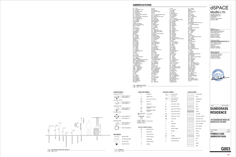
ABBREVIATIONS ABV ABOVE AFF ABOVE FINISH FLOOR AC ACCESSORIES ACF ACCESS FLOORING AP ACCESS PANEL ACT ACOUSTIC TILE AWT ACOUSTICAL WALL TREATMENT ADJ ADJUSTABLE AFCI ARC-FAULT CIRCUIT INTERPRETER A/CAIR CONDITIONING AHU AIR HANDLING UNIT ALT ALTERNATE ALUM ALUMINUM ANOD ANODIZED L ANGLE APPROX APPROXIMATE ARCH ARCHITECT(URE)(URAL) ATTCHATTACHMENT @ AT A/VAUDIOVISUAL AUTO AUTOMATIC AUX AUXILIARY AVG AVERAGE BQ BANQUETTE BHND BEHIND BN BENCH BLW BELOW BTW BETWEEN BVL BEVELED BYND BEYOND BLK(G)BLOCK(ING) BD BOARD BC BOOKCASE BS BOTH SIDES BOT BOTTOM BRKT BRACKET BLDG BUILDING B/ BOTTOM OF CAB/C CABINET CPT CARPET CLG CEILING CL CENTER LINE C/C CENTER TO CENTER CT CERAMIC TILE CH CHAIR CLR CLEAR CLST CLOSET CWCOLD WATER CWS COLD WATER SUPPLY COL COLUMN COMB COMBINATION COMPR COMPRESSION/COMPRESSIBLE CONC CONCRETE/CONCEALED CMU CONCRETE MASONRY UNIT CONN CONNECTION CJ CONSTRUCTION JOINT CONTROL JOINT CONT CONTINUOUS CONTR CONTRACTOR CONST CONSTRUCTION COORD COORDINATE CORRD CORRIDOR CTR COUNTER CR CREDENZA D DEPTH DK DESK DTL DETAIL DIAG DIAGONAL DIADIAMETER DIM DIMENSION DWDISHWASHER DISP DISPENSER DISTR DISTRIBUTION DIVDIVISION
DRAWING SYMBOLS
ANNOTATION SYMBOLS CENTERLINE
DRAWING NUMBER, TYP SHEET NUMBER, TYP
A501
ELECTRICAL SYMBOLS
DRAWING NUMBER, TYP SHEET NUMBER, TYP
A601
F# Z0
DOOR TAG
SINGLE OUTLET
CONCRETE
WINDOW TAG
WALL OUTLET - DUPLEX
CMU
WALL OUTLET - QUAD
EARTH
DUPLEX OUTLET & SWITCH
GRASS GRAVEL
ELEVATION TAG
FLOOR OUTLET - DUPLEX
GYP BOARD
FLOOR OUTLET - QUAD
INSULATION - BLOWN IN
DATA OUTLET
INSULATION - RIGID
J-BOX
INSULATION - SPRAY FOAM
THERMOSTAT
METAL - ALLUMINUM
INTERCOM
METAL - BRONZE
SECURITY CAMERA
METAL - STEEL
SPEAKER
MORTAR
TV
TV
PLASTIC
DB
DOORBELL
PLYWOOD
HANDING PENDANT LIGHT
SAND
WALL MNTD SCONCE
TILE
BASE CLG
ROOM TAG
FINISH SCHEDULE
18"
WALL FLOOR
24"
SD
24"
CO
SMOKE DETECTOR
CABINETRY
SHOWER HEAR
SHOWER CONTROLS
GOODFRIEND MAGRUDER STRUCTURE, LLC BOB MAGRUDER & ERIC WHITE
53 W. JACKSON BLVD. SUITE 340 CHICAGO, IL 60604 PHONE: 312.607.9898 GENERAL CONTRACTOR
ZAHN BUILDERS, INC TONY ZAHN & MATT BRUURSEMA
443 DOUGLAS AVE #40 HOLLAND, MI 49424 PHONE: 616.738.9246
SUPPLY AIR GRILLE NOMINAL LUMBER
RA
RETURN AIR GRILLE
NON-STANDARD LUMBER
SHOWER HEAD
BATT INSULATION
SHOWER CONTROL
MAIN ENTRY ARROW
ISSUE FOR PERMIT
DUNEGRASS RESIDENCE 195 DUNEGRASS RIDGE DR SAUGATUCK, MI 49453
HB
HOSE BIB
0244.01
PROJECT NUMBER:
CO DETECTOR
SA
ENTRY
STRUCTURAL ENGINEER
MECH & PLUMBING SYMBOLS
MISC SYMBOLS TOILET PAPER HOLDER
15" OUTLET (COORD W/ BASE TRIM
SPECIAL POWER OUTLET
36"
36" DOOR HANDLE
THERMOSTAT
SWITCH
REVISION (POST SIGNED CONTRACT)
SHEET NUMBER, TYP
AREA OF ENLARGEMENT
STANDARD MOUNTING HEIGHTS 3/8" = 1'-0"
A DATE
COORD W/ OWNER
VARIES
42" - 60" 60" 48"
46" TYP BATH TOWEL BAR
12"
ADDENDUM (PRE SIGNED CONTRACT)
ROOM NAME
DRAWING NUMBER, TYP SHEET NUMBER, TYP
A601
2920 N LINCOLN AVE CHICAGO, IL 60657 PHONE: 773.423.2920
CEMENT BOARD
1 DATE
DRAWING NUMBER, TYP
ENLARGED DRAWING 1
SWITCHING ZONE
KEVIN TOUKOUMIDIS, BOB MCFADDEN, JOSEPH KAFTAN, LILLIAN JONES, & HAYLEY BURROUGHS
LIGHT FIXTURE TAG
IC
ARCHITECT
dSPACE STUDIO LTD
BRICK
WALL / FLOOR / ROOF TAG
T/LOWER LEVEL
1 A401
www.dspacestudio.com info@dspacestudio.com 773.423.2920 2920 North Lincoln Avenue Chicago, IL 60657
ACOUSTIC PANEL
INTERIOR ELEVATION
studio LTD
07.08.25 DRAWING NUMBER, TYP SHEET NUMBER, TYP
A201
dSPACE
HATCH PATTERNS
EXTERIOR ELEVATION 1
SWITCHING ZONE LIGHT SWITCH
PROPERTY LINE
WALL / DETAIL SECTION 1
REV REVISION RH RIGHT HAND RM ROOM RO ROUGH OPENING RND ROUND RU RUG RUB RUBBER RESD RECESSES SCHED SCHEDULE(D) STG SEATING SECT SECTION SERV SERVICE SHT SHEET SIM SIMILAR SD SMOKE DAMPER/SMOKE DETECTOR SC SOLID CORE STC SOUND TRANSMISSION CLASS S SOUTH SPEC SPECIFICATION/SPECIAL SQ SQUARE SS STAINLESS STEEL STD STANDARD SNT SEALANT STL STEEL SO SOFA ST STONE STOR STORAGE STRUCT STRUCTURE/STRUCTURAL SUP SUPPORT SURF SURFACE SUSP SUSPENDED SWSWITCH SYM SYMMETRICAL TA TABLE TB TACKBOARD TEL TELEPHONE TEMP TEMPERED THK THICK(NESS) THRESTHRESHOLD T&G LOUNGE AND GROOVE T/ TOP OF T TREAD(S) TYP TYPICAL UC UNDERCUT UL UNDERWRITER'S LABORATORY UNFN UNFINISHED UNIF UNIFORM UNO UNLESS NOTED OTHERWISE UTIL UTILITY VB VAPOR BARRIER VAR VARIE(S)(D) VNR VENEER VERT VERTICAL VAT VINYL ASBESTOS TILE VCT VINYL COMPOSITION TILE VWC VINYL WALL COVERING VEST VESTIBULE WTW WALL TO WALL WCWATER CLOSET WHWATER HEATER WPWATER PROOF WGT/WT WEIGHT W WIDTH/WEST WIC WALK IN CLOSET. WIND WINDOW WW WINDOW WALL WT WINDOW TREATMENT W/ WITH W/O WITHOUT WDWOOD/WOOD VENEER WDB WORK STATION BASE YD YARD
ABBREVIATIONS 12" = 1'-0"
BUILDING / SITE SECTION 1
LA LAMP LAV LAVATORY LQ LACQUER LE LEATHER LH LEFT HAND LS LIBRARY SHELVING LT(G) LIGHT(ING) LTWT LIGHTWEIGHT LF LINEAR FOOT LK LOCKER LG/L LONG/LENGTH LP LAM LOW PRESSURE LAMINATE MFR MANUFACTURER MAS MASONRY ML MATCH LINE MATL MATERIAL MAX MAXIMUM MECH MECHANICAL MTL METAL MID MIDDLE MW MILLWORK MIN MINIMUM MISC MISCELLANEOUS MRB MARBLE MOD MODULE MLDG MOULDING MTD MOUNTED MTG MOUNTING MUL MULLION MP MOVEABLE PARTITION NRC NOISE REDUCTION COEFFICIENT NOM NOMINAL N NORTH NA NOT APPLICABLE NIC NOT IN CONTRACT NTS NOT TO SCALE NO NUMBER OFF OFFICE OC ON CENTER OPNG OPENING OPP OPPOSITE OPND OPENING OD OUTSIDE DIAMETER OF OUTSIDE FACE OA OVERALL OVHD OVERHEAD PA/PNT PAINT PTD PAINTED PNL PANEL PTR PRINTER PTN PARTITION PED PEDESTAL/STAND PL PLANT/PLANTER PLAS PLASTER PLAM PLASTIC LAMINATE PLYWD PLYWOOD POL POLISHED LB(S) POUND(S) PVC POLY VINYL CHLORIDE PSIPOUND PER SQUARE INCH QTY QUANTITY QT QUARRY TILE R RADIUS/RISER(S) RTD RATED RCVG RECEIVING RECPTRECEPTACLE RECEP RECEPTION REF REFER/REFERENCE REFL REFLECTED RA RETURNED AIR REINF REINFORCE(D)(ING) REQD REQUIRED RT RESILIENT TILE RB RESILIENT BASE
Z0
DR DOOR DN DOWN DWG DRAWING DF DRINKING FOUNTAIN EA EACH E EAST EDF ELECTRIC DRINKING FOUNTAIN ELEC ELECTRIC(AL) EWC ELECTRIC WATER COOLER EL ELEVATION ELEV ELEVATOR ENCL ENCLOSURE EQ EQUAL/EQUIPMENT EQUIP EQUIPMENT EXH EXHAUST EX EXISTING EJ EXPANSION JOINT EXP EXPOSED EXT EXTERIOR EXT'D EXTRUDED FA FABRIC FAB FABRICATION FTP FABRIC TRACK PANEL FWC FABRIC WALL COVERING FT FEET/FOOT FPHB FROST PROTECT HOSE BIB FINFINISH(ED) FF FINISHED FLOOR FE FIRE EXTINGUISHER FHV FIRE HOSE VALVE FP FIRE PROOF(ING) FIXT FIXTURE FL FLOOR FD FLOOR DRAIN FLMTDFLOOR MOUNTED FLOURFLUORESCENT FS FULL SIZE FUT FUTURE FDTN FOUNDATION GA GAGE/GAUGE GALV GALVANIZED GC GENERAL CONTRACTOR GL GLASS GR GRAPHICS GND GROUND GRT GROUT GYP BD GYP BOARD HCP HANDICAPPED HDW HARDWARE HDWD HARDWOOD HVAC HEATING, VENTILATION & AIR CONDITIONING HT/H HEIGHT HEX HEXAGONAL HM HOLLOW METAL HORIZ HORIZONTAL HR HOUR HC HOLLOW CORE HWHOT WATER INCAND INCANDESCENT INCL INCLUDE(D)(ING) INFO INFORMATION ID INSIDE DIAMETER INSIDE DIMENSION INSUL INSULATION INTINTERIOR JAN JANITOR JT JOINT J-BOX JUNCTION BOX KPL KICK PLATE KIT KITCHEN KO KNOCKOUT LBL LABEL LAM LAMINATE(D)
SCALE:
AS NOTED
SYMBOLS AND ABBREVIATIONS
WATER WOOD
SYMBOLS 12" = 1'-0"
G003 46
Page 47
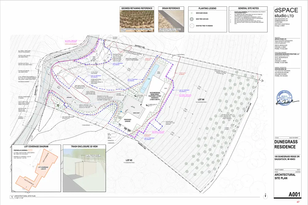
Text of page 47
GEOWEB RETAINING REFERENCE
DRAIN REFERENCE
GENERAL SITE NOTES
PLANTING LEGEND 1.
NEW DUNE GRASS 2. 3.
NEW TREE SAPLING
4. 5. 6.
DO NOT SCALE DRAWINGS. WRITTEN DIMENSIONS HOLD PRIORITY OVER APPARENT SCALE. ALL DIMENSIONS ARE TAKEN FROM THE FACE OF FINISH OR GRIDLINE UNLESS NOTED OTHERWISE. GC TO VERIFY ALL DIMENSIONS & CLEARANCES - NOTIFY ARCHITECT OF ANY DISCREPANCIES PRIOR TO PROCEEDING. REF A703 FOR LIGHT FIXTURE SCHEDULE REF STRUCTURE DRAWINGS FOR STRUCTURAL DETAILS. REF ARCHITECTURAL FLOOR PLAN FOR ADDITIONAL BUILDING INFO.
EXISTING TREE TO REMAIN
studio LTD www.dspacestudio.com info@dspacestudio.com 773.423.2920 2920 North Lincoln Avenue Chicago, IL 60657
STAINLESS STEEL GRATE TRENCH DRAIN (VEHICULAR GRADE) 10
P IR M
P 023
* SEA
A LT N
YA R
LSEA
,R O
D A ,& N C H SR O
N O T
B YT U
EB ILET
PRESTO GEOSYSTEMS - GEOWEB RETAINING WALL SYSTEM
dSPACE
25' FRONT SETBACK
KEVIN TOUKOUMIDIS, BOB MCFADDEN, JOSEPH KAFTAN, LILLIAN JONES, & HAYLEY BURROUGHS
SILT FENCE / TEMP SLOPE PROTECTION BOUNDARY
ARCHITECT
dSPACE STUDIO LTD
STEEP SLOPE BOUNDARY
PROPE E
E DUN
TEMP SAND STAGING AREA
E W
LIMIT OF TEMPORARY DISTURBANCE
195 DUNEGRASS RIDGE DRIVE: PROPOSED 2-STORY RESIDENCE (3 BED/3.5BATH)
IN
T/ POOL PATIO 682' - 2"
CH DR A
SILT FENCE / TEMP SLOPE PROTECTION BOUNDARY
LOT #4 195 DUNEGRASS RIDGE
16 '-
LI N
E E
TY
T/ LOWER LEVEL FF 680' - 11"
ST
NEW TRASH ENCLOSURE W/ WOOD GATE
DRIVE COURT
GREEN ROOF
82 NEW NATIVE TREE SAPLINGS PER APPROVED EGLE PERMIT DRAWINGS.
GASMAIN EASEMENT
SL OP
30' -
EE P SL OP E
SL OP
PR O PER
ASPHALT DRIVEWAY: 16FT WIDE & 10% SLOPE MAX PER SAUGATUCK FIRE DEPT
PROPOSED GARAGE -
EXISTING DECK STRUCTURE TO BE REMOVED
5' SIDE SETBACK
DRIVEWAY & SITE PLAN APPROVED BY FIRE DEPARTMENT: PLEASE REFERENCE APPROVAL DOCUMENT ON SHEET A/002.
GEOWEB RETAINING WALL
T GA
10' REAR SETBACK
GAS METER
LIMIT OF TEMPORARY DISTURBANCE
PR
CONDENSERS
TRASH ENCLOSURE 3D VIEW
OP E
07.08.25
RT
YL
ISSUE FOR PERMIT
DUNEGRASS RESIDENCE
GENERATOR
EE P SL OP E
STEEP SLOPE BOUNDARY
ST
SILT FENCE / TEMP SLOPE PROTECTION BOUNDARY
ELEC METER
LOT COVERAGE DIAGRAM
443 DOUGLAS AVE #40 HOLLAND, MI 49424 PHONE: 616.738.9246
ST EE P SL OP E
DECK
DRIVEWAY
STEEP SLOPE BOUNDARY
TONY ZAHN & MATT BRUURSEMA
POOL
LIMIT OF TEMPORARY DISTURBANCE
GUEST PARKING & TURNAROUND/TEMP SAND STAGING AREA
ZAHN BUILDERS, INC
DIREC TIO FORC NAL BORE EMAIN SEPT DRAIN , TO SHARE IC AGE F IELD D
TR EN
TY LINE P R OP E R
GENERAL CONTRACTOR P
TEMP SAND STAGING AREA: REPLANT AFTER CONSTRUCTION
CA BA TCH SIN
30' - 0"
EXISTING WATER SERVICE LINE UNDER STREET
SL OP
STORM WATER DRAIN CONNECTION TO DIRECTIONAL BORING TO LEACH BASIN
UTILITY LINES TO BE DIRECTIONALLY BORED UNDER STEEP SLOPE
EE
POOL PATIO
LIMIT OF TEMPORARY DISTURBANCE
EXISTING TRANSFORMER TO REMAIN
53 W. JACKSON BLVD. SUITE 340 CHICAGO, IL 60604 PHONE: 312.607.9898
STEEP SLOPE BOUNDARY
4'-0" DIA. ROCK LEACH BASIN
2' TALL ADDRESS SIGN (NUMBERS TO BE 6" TALL): GC TO ENSURE NUMBERS ARE CLEARLY VISIBLE FROM STREET. WATERMAIN EASEMENT
ST
EXISTING GAS SERVICE LINE UNDER STREET
BOB MAGRUDER & ERIC WHITE
68 0
GOODFRIEND MAGRUDER STRUCTURE, LLC
5' SIDE SETBACK
LIMIT OF TEMPORARY DISTURBANCE
EXISTING ELECTRICAL SERVICE LINE UNDER STREET
SS GR A
STRUCTURAL ENGINEER
EXISTING CABLE SERVICE LINE UNDER STREET
INE
DIREC T I O NA L TO SH BORE SEP T ARED DRAIN IC FORCEM AIN, AGE F PROPOSED SEPTIC 5' IELD X 8' (1000 GAL) TANKS EACH, 2 FT APART. TANKS ARE MORE DIRECTIONAL BORE ELEC THAN 75 FT FROM TO SEPTIC PUMP CHAMBER CREST OF DUNE
DRIVE E G C RID
2920 N LINCOLN AVE CHICAGO, IL 60657 PHONE: 773.423.2920
SILT FENCE / TEMP SLOPE PROTECTION BOUNDARY
RT Y L
IN E
• PROPOSED LOT COVERAGE =
OR
BE
LO W
• LOT AREA = 66,615 SF (PER 11/05/24 SURVEY) REF. SHEET SP.2 FOR SURVEY
4'-0" TALL TRASH ENCLOSURE: CLADDING TO MATCH RESIDENCE
195 DUNEGRASS RIDGE DR SAUGATUCK, MI 49453
LIN E
OF
FLO
• MAXIMUM LOT COVERAGE = 3,331 SF (0.05 × 66,615 SF = 3,331 SF)
LOT #3 175 DUNEGRASS RIDGE
LOT COVERAGE: 3,262 SF
0244.01
PROJECT NUMBER: SCALE:
ARCHITECTURAL SITE PLAN OF
FLO
OR
BE
LO W
NIC HE
LIN E
AS NOTED
HB
ARCHITECTURAL SITE PLAN 1/16" = 1'-0"
A001 47
Page 48
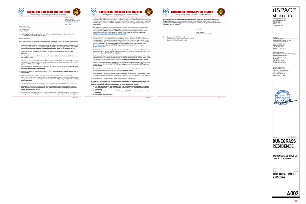
Text of page 48
dSPACE studio LTD www.dspacestudio.com info@dspacestudio.com 773.423.2920 2920 North Lincoln Avenue Chicago, IL 60657
ARCHITECT
dSPACE STUDIO LTD KEVIN TOUKOUMIDIS, BOB MCFADDEN, JOSEPH KAFTAN, LILLIAN JONES, & HAYLEY BURROUGHS
2920 N LINCOLN AVE CHICAGO, IL 60657 PHONE: 773.423.2920 STRUCTURAL ENGINEER
GOODFRIEND MAGRUDER STRUCTURE, LLC BOB MAGRUDER & ERIC WHITE
53 W. JACKSON BLVD. SUITE 340 CHICAGO, IL 60604 PHONE: 312.607.9898 GENERAL CONTRACTOR
ZAHN BUILDERS, INC TONY ZAHN & MATT BRUURSEMA
443 DOUGLAS AVE #40 HOLLAND, MI 49424 PHONE: 616.738.9246
07.08.25
ISSUE FOR PERMIT
DUNEGRASS RESIDENCE 195 DUNEGRASS RIDGE DR SAUGATUCK, MI 49453
PROJECT NUMBER: SCALE:
0244.01 AS NOTED
FIRE DEPARTMENT APPROVAL
A002 48
Page 49
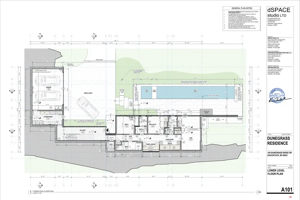
Text of page 49
GENERAL PLAN NOTES 1. 2. 3. 4. 5. 6. 7. 8. 9.
A501
A501
5.1
5.4
7.2
dSPACE
DO NOT SCALE DRAWINGS. WRITTEN DIMENSIONS HOLD PRIORITY OVER APPARENT SCALE. ALL DIMENSIONS ARE TAKEN FROM THE FACE OF FINISH OR GRIDLINE UNLESS NOTED OTHERWISE. GC TO VERIFY ALL DIMENSIONS & CLEARANCES - NOTIFY ARCHITECT OF ANY DISCREPANCIES PRIOR TO PROCEEDING. GC TO MARK WALL LOCATIONS ON FLOOR PRIOR TO ERECTING INTERIOR WALLS FOR OWNER / ARCHITECT REVIEW. GC TO COORD FRAMING & STRUCTURAL LAYOUT WITH PLUMBING, HVAC & ELEC TO AVOID CONFLICTS. REF A700 FOR FINISH SCHEDULE REF STRUCTURAL DRAWINGS FOR STRUCTURAL DETAILS. REF MEP DRAWINGS FOR ADDITIONAL MEP INFO REF ARCHITECTURAL SITE PLAN FOR ADDITIONAL SITE INFO.
studio LTD www.dspacestudio.com info@dspacestudio.com 773.423.2920 2920 North Lincoln Avenue Chicago, IL 60657
ARCHITECT
dSPACE STUDIO LTD KEVIN TOUKOUMIDIS, BOB MCFADDEN, JOSEPH KAFTAN, LILLIAN JONES, & HAYLEY BURROUGHS
109' - 11" 15' - 10"
5' - 6"
5' - 0"
21' - 11"
4 1/2"
6' - 5"
14' - 6"
18' - 6"
2' - 7"
19' - 3 1/2"
25' - 11"
2920 N LINCOLN AVE CHICAGO, IL 60657 PHONE: 773.423.2920 STRUCTURAL ENGINEER
GOODFRIEND MAGRUDER STRUCTURE, LLC BOB MAGRUDER & ERIC WHITE
53 W. JACKSON BLVD. SUITE 340 CHICAGO, IL 60604 PHONE: 312.607.9898
TRENCH DRAIN
19' - 3"
33' - 2" FIRE ALARM HORN/STROBE
X2
GENERAL CONTRACTOR
ZAHN BUILDERS, INC TONY ZAHN & MATT BRUURSEMA
5' - 0"
B C
ELEV 112
7' - 9"
6' - 2"
17' - 5"
6' - 2 3/4"
X1
6C
4H
HALL 113
COAT 4A CLST ELEV EQP
4B
4A
4H
4H
MILLWORK BENCH UP
10' - 4 1/2"
GLASS GUARDRAIL PROVIDES 48" MIN. CONT. POOL BARRIER PER ISPSC SEC. 305
5' - 1 1/2" 5' - 0 1/2"
54' - 6"
AUTOCOVER
4' - 10 1/2"
SHELVES
0' - 0"
CAB
GYM 107
107A
4 A501 07.08.25
4B
BUNK ROOM 109 GAME LOUNGE 110
48" BARRIER AT GATE
1' - 3"
6B
4' - 0"
DESK
KITCHENETTE
SAUNA 108 108
CONC. WALKWAY
X1 4B
6A
0' - 0"
BANQUETTE DH
6D
106A
6B
FURNACE (48"x48")
FD
106C
BATH-3 106 4B
104A
MECH 111
SHOWER
6A
POOL EQUIP
21' - 7"
6B
107B
6D
4D
6D
5' - 2 1/2"
PORTAL
6A
SCULPTURE GARDEN
X2 BUNK BEDS
DUNEGRASS RESIDENCE
6F CAB
ISSUE FOR PERMIT
6' - 2"
6C
BED-3/FLEX 105
104B
103A
SLIDING
6D
104C
BATH-2 104
19T @ 10" 20R @ 7-1/8"
6' - 0"
SHOWER
4B
12' - 0"
CLERESTORY
6D
6D
4' - 0"
UP
4' - 0"
5' - 2 1/2"
X2
0' - 0"
BED-2 103
ENTRY
4' - 4"
GALLERY 102
8' - 6"
15' - 10"
11' - 3 1/2"
FIRE DEPARTMENT KNOX BOX
101B
X2
2' - 3"
D2
CLST
1/2" THICK X 8" TALL PAINTED STEEL EDGING (CURB STOP FOR VEHICLES).
4B
W/D W/D (STACKED) (STACKED)
G 4' - 10 1/2"
CLOSET 103B
0' - 0" X4
TALL CAB
D1
2' - 6 1/2"
CLERESTORY
101C
X2
6' - 10 1/2"
8' - 11"
LAUNDRY/MUD 101
B2
B1
14' - 3"
HB
10' - 2"
AV CLST
UP
0' - 0"
5' - 0"
3' - 3 1/2"
TALL CAB
12' - 8 1/2"
3' - 8 1/2"
TALL CAB
5' - 0"
4' - 1 1/2"
TALL CAB
2' - 3"
BOILER
BENCH
5' - 4 1/4"
5' - 0 1/2"
54' - 6"
11' - 3"
101A
A501
1' - 3"
X4
6' - 10 1/2"
19' - 3"
LINE OF LEVEL ABOVE
103B
5' - 1 1/2"
-0' - 0 3/4"
6B
48" SAFTEY BARRIER AT GATE
UP
POOL (50x8)
BAJA LEDGE
8' - 0"
DRIVE COURT
SPA (7X8)
10' - 6"
FOOTWASH STATION
X2
5' - 1"
DN
GLASS GUARDRAIL PROVIDES 48" MIN. CONT. POOL BARRIER PER ISPSC SEC. 305
GARAGE 100
26' - 3"
A501
A501
50' - 0" VERTICAL DROP FROM POOL EDGE TO ADJACENT GRADE PROVIDES 48" MIN. CONT. BARRIER PER ISPSC SEC. 305.
26' - 2 1/2"
10' - 4 1/2"
3' - 0"
1' - 6"
7' - 0"
1' - 10"
443 DOUGLAS AVE #40 HOLLAND, MI 49424 PHONE: 616.738.9246
9' - 0"
9' - 0"
GLENN'S WORK STATION
1' - 10"
HB
2.5" POST-MOUNTED FDC (FIRE DEPARTMENT CONNECTION)
BUNK BEDS
ERV CLERESTORY
X1
4' - 1 1/4"
4' - 10"
X2
12' - 9 5/8" 16' - 10 7/8"
195 DUNEGRASS RIDGE DR SAUGATUCK, MI 49453
X2
10' - 7"
13' - 4 1/4"
11' - 11 1/2"
PROJECT NUMBER:
0244.01
SCALE:
AS NOTED
LOWER LEVEL FLOOR PLAN 15' - 10"
1 A501
LOWER LEVEL FLOOR PLAN 3/16" = 1'-0"
5' - 6"
5' - 0"
21' - 11"
4 1/2"
2 A501
6' - 5"
5.1
14' - 6"
5.4
18' - 6"
2' - 7"
19' - 3 1/2"
7.2
25' - 11"
TRU
RTH E NO
A101 49
Page 50
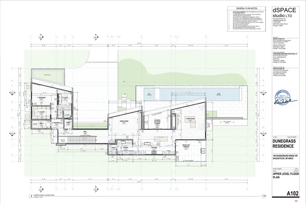
Text of page 50
GENERAL PLAN NOTES 1. 2. 3. 4. 5. 6. 7. 8. 9.
A501
A501
5.1
5.4
7.2
dSPACE
DO NOT SCALE DRAWINGS. WRITTEN DIMENSIONS HOLD PRIORITY OVER APPARENT SCALE. ALL DIMENSIONS ARE TAKEN FROM THE FACE OF FINISH OR GRIDLINE UNLESS NOTED OTHERWISE. GC TO VERIFY ALL DIMENSIONS & CLEARANCES - NOTIFY ARCHITECT OF ANY DISCREPANCIES PRIOR TO PROCEEDING. GC TO MARK WALL LOCATIONS ON FLOOR PRIOR TO ERECTING INTERIOR WALLS FOR OWNER / ARCHITECT REVIEW. GC TO COORD FRAMING & STRUCTURAL LAYOUT WITH PLUMBING, HVAC & ELEC TO AVOID CONFLICTS. REF A700 FOR FINISH SCHEDULE REF STRUCTURAL DRAWINGS FOR STRUCTURAL DETAILS. REF MEP DRAWINGS FOR ADDITIONAL MEP INFO REF ARCHITECTURAL SITE PLAN FOR ADDITIONAL SITE INFO.
studio LTD www.dspacestudio.com info@dspacestudio.com 773.423.2920 2920 North Lincoln Avenue Chicago, IL 60657
ARCHITECT
dSPACE STUDIO LTD KEVIN TOUKOUMIDIS, BOB MCFADDEN, JOSEPH KAFTAN, LILLIAN JONES, & HAYLEY BURROUGHS
135' - 10" 15' - 10"
5' - 6"
5' - 0"
21' - 11"
4 1/2"
6' - 5"
14' - 6"
18' - 6"
2' - 7"
19' - 3 1/2"
2920 N LINCOLN AVE CHICAGO, IL 60657 PHONE: 773.423.2920
25' - 11"
STRUCTURAL ENGINEER
GOODFRIEND MAGRUDER STRUCTURE, LLC BOB MAGRUDER & ERIC WHITE
53 W. JACKSON BLVD. SUITE 340 CHICAGO, IL 60604 PHONE: 312.607.9898
GENERAL CONTRACTOR
ZAHN BUILDERS, INC
443 DOUGLAS AVE #40 HOLLAND, MI 49424 PHONE: 616.738.9246
9' - 0"
9' - 0"
TONY ZAHN & MATT BRUURSEMA
GREEN ROOF
1' - 10"
B 1' - 10"
B ELEC
2' - 11 1/2"
6C X3
K 4' - 0"
X3
PANTRY 212 48" REF/FRZ
4' - 9 1/4"
DUAL OVEN
APP GARAGE
9' - 5"
30" TALL CAB
30" FRZ
6' - 7 1/4"
KITCHEN 211 30" REF
7' - 10 3/8"
9' - 11 1/8"
STEAM OVEN
30" TALL CAB
X3
10' - 7"
10' - 4 1/2" 4' - 10 1/2"
9' - 8"
12' - 1 3/4"
3' - 3 7/8"
4' - 9"
7' - 9 3/4"
26' - 6 1/2"
5' - 2 1/2"
MICROWAVE
DW
58' - 6"
A501
X3
DUNEGRASS RESIDENCE
WOODLAND TERRACE 210
X3
K 42" GLASS GUARDRAIL
15' - 9"
195 DUNEGRASS RIDGE DR SAUGATUCK, MI 49453
L 3' - 3 1/2" PROJECT NUMBER: SCALE:
15' - 10"
5' - 6"
5' - 0"
21' - 11"
4 1/2"
6' - 5"
14' - 6"
18' - 6"
2' - 7"
ISSUE FOR PERMIT
6' - 2"
TRASH
4' - 0"
31' - 0 7/8"
ELEV ELEV.
6A
3' - 7"
7' - 8 3/4"
9' - 4 3/8" 2' - 2 1/2"4' - 2 3/4"
17' - 4"
6' - 4 1/8"
6' - 0 1/8"
WINE
13' - 4"
X3
TRASH
07.08.25
42" GLASS GUARDRAIL
DW
BAR SEATING
3' - 9"
4A
CONC. WALKWAY (BELOW)
4F
6' - 2"
11' - 2"
2' - 2 1/2"
6C
LIVING ROOM 209
6' - 10 1/2"
11' - 11 3/8"
8' - 1 5/8"
10' - 11 1/2"
13' - 2"
4' - 1"
4F
6B
19T @ 10" 20R @ 7-1/8"
OPEN TO BELOW
6' - 2"
COVERED OUTDOOR LOUNGE 208
36" GLASS GUARDRAIL
4' - 0"
4' - 1"
5' - 11 1/2"
4' - 9 1/2"
2' - 5 3/4"
8' - 5 7/8"
3' - 4"
HALL 206
2' - 6 1/2"
4' - 0"
6D
11' - 6 1/2"
X3
4F
208B
X3
5' - 2 1/2"
X3 X3
4' - 10 1/2"
21' - 9"
7' - 9"
ERV
ART
PWDR 205
6' - 2"
P. VESTIBULE 6D 204
DN
DH
HB
MECH 203
DINING ROOM 207
X3
6B
5' - 0"
5' - 0"
6' - 10 1/2"
FURNACE (48"x 48")
IL
BENCH
6B HW
A ARDR
23' - 1 1/2"
42"
200 A/C
POOL EQUIP (BELOW)
SHOWER
S GU GLAS
4F
FP W/ TV ABV
6D
5' - 0 1/2"
6B
GRILL
4' - 6"
X3
201D
TLT
8H
4' - 10 1/2"
2' - 1"
8' - 1"
MAKE UP
CLERESTORY
5' - 0 1/2"
58' - 6"
6A
201C
P. CLOSET 202
4D
8' - 5 1/4"
11"
1' - 6"
GEN
1' - 1"
2' - 1"
6A
A501
16' - 7"
19' - 4 1/2"
5' - 1"
5' - 1 1/2"
6A
20' - 5"
POOL (BELOW)
18' - 4 1/2"
5' - 1 1/2"
6B
A/C
A501
6B
X3
P. BATH TUB 201
2' - 8"
10' - 2"
P. BEDROOM 200
SPA (BELOW)
3' - 9"
11' - 0"
21' - 0 1/2"
8' - 4"
SKYLIGHT ABOVE
12' - 1"
201A
201B
15' - 10"
1' - 5 1/2"
A501
12' - 7 1/2"
10' - 4 1/2"
14' - 0 1/2"
GAS
19' - 3 1/2"
0244.01 AS NOTED
UPPER LEVEL FLOOR PLAN
25' - 11"
135' - 10"
1 A501
UPPER LEVEL FLOOR PLAN 3/16" = 1'-0"
2 A501
5.1
5.4
7.2
TRU
RTH E NO
A102 50
Page 51
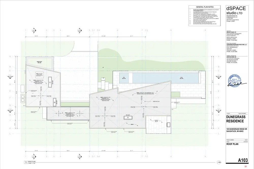
Text of page 51
GENERAL PLAN NOTES 1. 2. 3. 4. 5. 6. 7. 8. 9.
A501
A501
5.1
5.4
7.2
dSPACE
DO NOT SCALE DRAWINGS. WRITTEN DIMENSIONS HOLD PRIORITY OVER APPARENT SCALE. ALL DIMENSIONS ARE TAKEN FROM THE FACE OF FINISH OR GRIDLINE UNLESS NOTED OTHERWISE. GC TO VERIFY ALL DIMENSIONS & CLEARANCES - NOTIFY ARCHITECT OF ANY DISCREPANCIES PRIOR TO PROCEEDING. GC TO MARK WALL LOCATIONS ON FLOOR PRIOR TO ERECTING INTERIOR WALLS FOR OWNER / ARCHITECT REVIEW. GC TO COORD FRAMING & STRUCTURAL LAYOUT WITH PLUMBING, HVAC & ELEC TO AVOID CONFLICTS. REF A700 FOR FINISH SCHEDULE REF STRUCTURAL DRAWINGS FOR STRUCTURAL DETAILS. REF MEP DRAWINGS FOR ADDITIONAL MEP INFO REF ARCHITECTURAL SITE PLAN FOR ADDITIONAL SITE INFO.
studio LTD www.dspacestudio.com info@dspacestudio.com 773.423.2920 2920 North Lincoln Avenue Chicago, IL 60657
ARCHITECT
dSPACE STUDIO LTD 15' - 10"
32' - 5"
21' - 3 1/2"
KEVIN TOUKOUMIDIS, BOB MCFADDEN, JOSEPH KAFTAN, LILLIAN JONES, & HAYLEY BURROUGHS
21' - 1"
2920 N LINCOLN AVE CHICAGO, IL 60657 PHONE: 773.423.2920 STRUCTURAL ENGINEER
GOODFRIEND MAGRUDER STRUCTURE, LLC BOB MAGRUDER & ERIC WHITE
53 W. JACKSON BLVD. SUITE 340 CHICAGO, IL 60604 PHONE: 312.607.9898
GENERAL CONTRACTOR
ZAHN BUILDERS, INC TONY ZAHN & MATT BRUURSEMA
443 DOUGLAS AVE #40 HOLLAND, MI 49424 PHONE: 616.738.9246
GREEN ROOF (BELOW)
C NOTE: NO ROOF DRAINS ABOVE BEDROOMS, TYP
A501
OVERFLOW SCUPPER; COORD W/ ARCH
38' - 3" ROOF-1: SINGLE-PLY TPO MEMBRANE, FULLY ADHERED OVER SLOPED RIGID INSULATION
NICHE
SLOPE TO DRAIN 1/4" PER 1'-0" MIN
ROOF-1: SINGLE-PLY TPO MEMBRANE, FULLY ADHERED OVER SLOPED RIGID INSULATION
SKYLIGHT
BB
A501 OVERFLOW SCUPPER; COORD W/ ARCH
10' - 1"
OVERFLOW SCUPPER; COORD W/ ARCH
ROOF-1: SINGLE-PLY TPO MEMBRANE, FULLY ADHERED OVER SLOPED RIGID INSULATION
RD
RD
SLOPE TO DRAIN 1/4" PER 1'-0" MIN
RD
4 A501
RD
SLOPE TO DRAIN 1/4" PER 1'-0" MIN
SLOPE TO DRAIN 1/4" PER 1'-0" MIN HB
F FIREPLACE FLUE
SLOPE TO DRAIN 1/4" PER 1'-0" MIN
HB
SLOPE TO DRAIN 1/4" PER 1'-0" MIN
SLOPE TO DRAIN 1/4" PER 1'-0" MIN
RD
SLOPE TO DRAIN 1/4" PER 1'-0" MIN
SLOPE TO DRAIN 1/4" PER 1'-0" MIN
10' - 1"
54' - 6"
54' - 6"
CC
SLOPE TO DRAIN 1/4" PER 1'-0" MIN
38' - 3"
ROOF-1: SINGLE-PLY TPO MEMBRANE, FULLY ADHERED OVER SLOPED RIGID INSULATION
A501
POOL (BELOW)
SKYLIGHT
SPA (BELOW)
SKYLIGHT SLOPE TO DRAIN 1/4" PER 1'-0" MIN
AA
07.08.25
6' - 2"
SLOPE TO DRAIN 1/4" PER 1'-0" MIN
6' - 2"
OVERFLOW SCUPPER; COORD W/ ARCH
DUNEGRASS RESIDENCE
TERRACE BELOW ROOF-1
K OVERFLOW SCUPPER; COORD W/ ARCH
ISSUE FOR PERMIT
195 DUNEGRASS RIDGE DR SAUGATUCK, MI 49453
OVERFLOW SCUPPER; COORD W/ ARCH
0244.01
PROJECT NUMBER: SCALE:
AS NOTED
ROOF PLAN 15' - 10"
1 A501
ROOF PLAN 3/16" = 1'-0"
32' - 5"
21' - 3 1/2"
2 A501
5.1
5.4
21' - 1"
7.2
TRU
RTH E NO
A103 51
Page 52
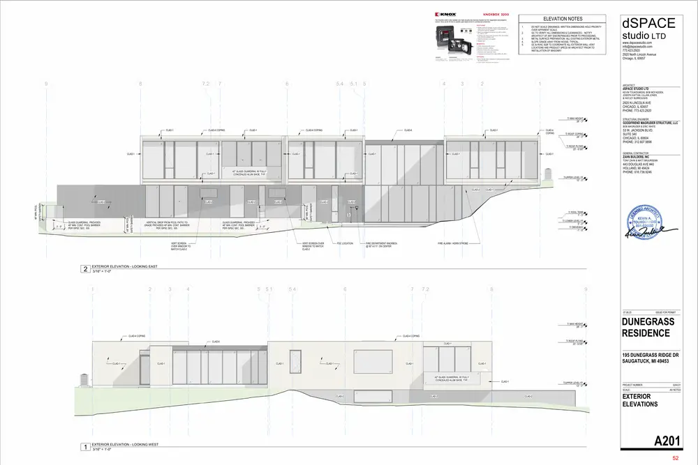
Text of page 52
ELEVATION NOTES 1. 2. 3. 4. 5.
7.2
5.4
5.1
DO NOT SCALE DRAWINGS. WRITTEN DIMENSIONS HOLD PRIORITY OVER APPARENT SCALE. GC TO VERIFY ALL DIMENSIONS & CLEARANCES - NOTIFY ARCHITECT OF ANY DISCREPANCIES PRIOR TO PROCEEDING. METAL SURFACE PREPARATION -ALL EXISTING EXTERIOR METAL SLOPE GRADE AWAY FROM HOUSE, TYPICAL. GC & HVAC SUB TO COORDINATE ALL EXTERIOR WALL VENT LOCATIONS AND PRODUCT SPECS W/ ARCHITECT PRIOR TO INSTALLATION OF MASONRY.
dSPACE studio LTD www.dspacestudio.com info@dspacestudio.com 773.423.2920 2920 North Lincoln Avenue Chicago, IL 60657
ARCHITECT
dSPACE STUDIO LTD KEVIN TOUKOUMIDIS, BOB MCFADDEN, JOSEPH KAFTAN, LILLIAN JONES, & HAYLEY BURROUGHS
2920 N LINCOLN AVE CHICAGO, IL 60657 PHONE: 773.423.2920 T/ MAX HEIGHT 28' - 3"
STRUCTURAL ENGINEER
GOODFRIEND MAGRUDER STRUCTURE, LLC BOB MAGRUDER & ERIC WHITE
CLAD-1
CLAD-4 COPING
CLAD-1
CLAD-4 COPING
CLAD-1
CLAD-6
CLAD-4 COPING
CLAD-1
53 W. JACKSON BLVD. SUITE 340 CHICAGO, IL 60604 PHONE: 312.607.9898
T/ ROOF COPING 24' - 0"
T/ ROOF PLYWD 23' - 6 5/8" CLAD-1
CLAD-1
CLAD-1
CLAD-1
CLAD-1
GENERAL CONTRACTOR
CLAD-1
ZAHN BUILDERS, INC TONY ZAHN & MATT BRUURSEMA
CLAD-1
42" GLASS GUARDRAIL W/ FULLY CONCEALED ALUM SHOE, TYP.
443 DOUGLAS AVE #40 HOLLAND, MI 49424 PHONE: 616.738.9246
CLAD-1 T/UPPER LEVEL FF 12' - 0"
GLASS GUARDRAIL PROVIDES 48" MIN. CONT. POOL BARRIER PER ISPSC SEC. 305
VERTICAL DROP FROM POOL PATIO TO GRADE PROVIDES 48" MIN. CONT. BARRIER PER ISPSC SEC. 305.
GLASS GUARDRAIL PROVIDES 48" MIN. CONT. POOL BARRIER PER ISPSC SEC. 305
CLAD-2
T/ POOL TERR 1' - 3" T/ LOWER LEVEL FF 0' - 0" T/ DRIVEWAY -1' - 9"
3' - 0"
VERT SCREEN OVER WINDOW TO MATCH CLAD-2
CLAD-2
CLAD-1
50"
CLAD-2
SAFETY BARRIER
CLAD-2
48" MIN. POOL
SAFETY BARRIER
3' - 0"
CLAD-2
48" MIN. POOL
CLAD-2
SAFETY BARRIER
48" MIN. POOL
CLAD-2
VERT SCREEN OVER WINDOW TO MATCH CLAD-2
FDC LOCATION
FIRE DEPARTMENT KNOXBOX @ 50" A.F.F. ON CENTER
FIRE ALARM / HORN STROBE
EXTERIOR ELEVATION - LOOKING EAST 3/16" = 1'-0"
5.1
5.4
7.2
07.08.25
T/ MAX HEIGHT 28' - 3"
CLAD-4 COPING
CLAD-4 COPING CLAD-6
CLAD-1
CLAD-1
CLAD-1
CLAD-1
195 DUNEGRASS RIDGE DR SAUGATUCK, MI 49453
CLAD-1
42" GLASS GUARDRAIL W/ FULLY CONCEALED ALUM SHOE, TYP.
DUNEGRASS RESIDENCE
T/ ROOF PLYWD 23' - 6 5/8"
CLAD-1
CLAD-1
ISSUE FOR PERMIT
CLAD-1
T/UPPER LEVEL FF 12' - 0"
PROJECT NUMBER:
0244.01
SCALE:
CLAD-2
EXTERIOR ELEVATION - LOOKING WEST 3/16" = 1'-0"
CLAD-2
CLAD-2
AS NOTED
EXTERIOR ELEVATIONS
A201 52
Page 53
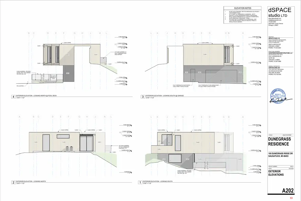
Text of page 53
ELEVATION NOTES 1. 2. 3. 4. 5.
DO NOT SCALE DRAWINGS. WRITTEN DIMENSIONS HOLD PRIORITY OVER APPARENT SCALE. GC TO VERIFY ALL DIMENSIONS & CLEARANCES - NOTIFY ARCHITECT OF ANY DISCREPANCIES PRIOR TO PROCEEDING. METAL SURFACE PREPARATION -ALL EXISTING EXTERIOR METAL SLOPE GRADE AWAY FROM HOUSE, TYPICAL. GC & HVAC SUB TO COORDINATE ALL EXTERIOR WALL VENT LOCATIONS AND PRODUCT SPECS W/ ARCHITECT PRIOR TO INSTALLATION OF MASONRY.
C B
T/ MAX HEIGHT 28' - 3"
CLAD-4 COPING
T/ ROOF COPING 24' - 0"
CLAD-1
T/ ROOF COPING 24' - 0" CLAD-1
T/ ROOF PLYWD 23' - 6 5/8"
CLAD-1
T/ ROOF PLYWD 23' - 6 5/8"
CLAD-1
ARCHITECT
dSPACE STUDIO LTD KEVIN TOUKOUMIDIS, BOB MCFADDEN, JOSEPH KAFTAN, LILLIAN JONES, & HAYLEY BURROUGHS
2920 N LINCOLN AVE CHICAGO, IL 60657 PHONE: 773.423.2920
GOODFRIEND MAGRUDER STRUCTURE, LLC
CLAD-1
BOB MAGRUDER & ERIC WHITE
T/UPPER LEVEL FF 12' - 0"
CLAD-1
www.dspacestudio.com info@dspacestudio.com 773.423.2920 2920 North Lincoln Avenue Chicago, IL 60657
STRUCTURAL ENGINEER
42" GLASS GUARDRAIL W/ FULLY CONCEALED ALUM SHOE SUPPORT
CLAD-1
studio LTD
T/ MAX HEIGHT 28' - 3"
CLAD-4 COPING
dSPACE
T/UPPER LEVEL FF 12' - 0"
CLAD-1
53 W. JACKSON BLVD. SUITE 340 CHICAGO, IL 60604 PHONE: 312.607.9898 GENERAL CONTRACTOR
ZAHN BUILDERS, INC
48" MIN. POOL
GLASS GUARDRAIL PROVIDES 48" MIN. CONT. POOL BARRIER PER ISPSC SEC. 305
SAFTEY BARRIER
TONY ZAHN & MATT BRUURSEMA CLAD-2
CLAD-2 48" SAFTEY BARRIER AT GATE
T/ LOWER LEVEL FF 0' - 0" T/ DRIVEWAY -1' - 9"
FULLY CONCEALED & FLUSH DOOR W/ CLAD-2 FINISH TO MATCH FACADE
EXTERIOR ELEVATION - LOOKING NORTH @ POOL DECK 3/16" = 1'-0"
T/ LOWER LEVEL FF 0' - 0" T/ GARAGE FF -0' - 7 1/2"
FULLY CONCEALED & FLUSH GARAGE DOOR W/ CLAD-2 FINISH TO MATCH FACADE
EXTERIOR ELEVATION - LOOKING SOUTH @ GARAGE 3/16" = 1'-0"
T/ MAX HEIGHT 28' - 3"
CLAD-1
CLAD-6
CLAD-4 COPING
T/ MAX HEIGHT 28' - 3"
CLAD-1
CLAD-4 COPING
CLAD-1
CLAD-4 COPING
T/ ROOF COPING 24' - 0"
T/ ROOF COPING 24' - 0"
T/ ROOF PLYWD 23' - 6 5/8"
T/ ROOF PLYWD 23' - 6 5/8"
CLAD-1
CLAD-1 42" GLASS GUARDRAIL W/ FULLY CONCEALED ALUM SHOE, TYP.
CLAD-1
CLAD-1
CLAD-1
T/UPPER LEVEL FF 12' - 0"
195 DUNEGRASS RIDGE DR SAUGATUCK, MI 49453 CLAD-2
CLAD-2
48" MIN. POOL
CLAD-2
GLASS GUARDRAIL PROVIDES 48" MIN. CONT. POOL BARRIER PER ISPSC SEC. 305
T/ DRIVEWAY -1' - 9"
EXTERIOR ELEVATION - LOOKING NORTH 3/16" = 1'-0"
ISSUE FOR PERMIT
T/UPPER LEVEL FF 12' - 0"
CLAD-2
07.08.25
DUNEGRASS RESIDENCE
CLAD-1
SAFTEY BARRIER
CLAD-4 COPING
CLAD-1
443 DOUGLAS AVE #40 HOLLAND, MI 49424 PHONE: 616.738.9246
CLAD-2
T/ POOL TERR 1' - 3"
FDC LOCATION
CLAD-2
T/ POOL TERR 1' - 3" T/ LOWER LEVEL FF 0' - 0" T/ DRIVEWAY -1' - 9"
0244.01
PROJECT NUMBER: SCALE:
AS NOTED
EXTERIOR ELEVATIONS
EXTERIOR ELEVATION - LOOKING SOUTH 3/16" = 1'-0"
A202 53
Page 54
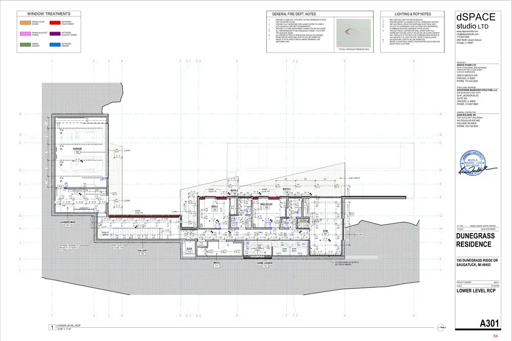
Text of page 54
GENERAL FIRE DEPT. NOTES
WINDOW TREATMENTS 1. MANUAL SOLAR SHADES
MOTORIZED SOLAR SHADES
PROVIDE A COMPLETE TYPE NFPA 13D FIRE SPRINKLER SYSTEM FOR THE ENTIRE HOUSE. PROVIDE FULLY MONITERED FIRE ALARM SYSTEM TO COMPLY WITH SAUGATUK FIRE DEPT REQUIREMENTS. PROVIDE 2-1/2" FIRE DEPARTMENT CONNECTION ON THE HOUSE ALL FIRESPRINKLERS TO BE CONCEALED, FLANGE - STYLE PER THE ADJACENT IMAGE ALL SPRINKLER PIPES TO RUN WITHIN CEILING, NO EXPOSED PIPING AND NO ADDITIONAL SOFFITS WILL BE PERMITTED. REFER TO RCPS SHEETS AND PLUMBING DRAWINGS FOR ADDITIONAL INFO
2. 3. 5.
MANUAL BLACKOUT SHADES
MOTORIZED BLACKOUT SHADES
6. 7.
MANUAL DRAPERY
LIGHTING & RCP NOTES 1. 2. 3. 4. 5.
6. 7.
MOTORIZED DRAPERY
dSPACE
REF A703 FOR LIGHT FIXTURE SCHEDULES. PROVIDE BUDGET ALLOWANCE FOR ALL LANDSCAPE LIGHTING. REF ELECTRICAL DWGS FOR ADDITIONAL ELECTRICAL INFO. GC & EC TO COORDINATE LIGHT FIXTURES WITH MECHANICAL , PLUMBING & RELATED EQUIPMENT IN THE CEILING. THE ELECTRICAL CONTRACTOR SHALL SPRAY PAINT FULL DOWNLIGHT FIXTURE LAYOUT ON CEILING OR FLOOR & IDENTIFY ANY CONFLICTS IN THE FIELD FOR COORDINATION & REVIEW W/ THE ARCHITECT & CLIENT ON SITE, PRIOR TO INSTALLATION. NO ADDITIONAL SOFFITS WILL BE PERMITTED. REFER TO ELECTRICAL SHEETS AND INTERIOR ELEVATIONS FOR RECEPTACLE LOCATIONS
studio LTD www.dspacestudio.com info@dspacestudio.com 773.423.2920 2920 North Lincoln Avenue Chicago, IL 60657
TYPICAL CONCEALED SPRINKLER HEAD
5.1
5.4
7.2
ARCHITECT
dSPACE STUDIO LTD KEVIN TOUKOUMIDIS, BOB MCFADDEN, JOSEPH KAFTAN, LILLIAN JONES, & HAYLEY BURROUGHS
2920 N LINCOLN AVE CHICAGO, IL 60657 PHONE: 773.423.2920 STRUCTURAL ENGINEER
GOODFRIEND MAGRUDER STRUCTURE, LLC BOB MAGRUDER & ERIC WHITE
53 W. JACKSON BLVD. SUITE 340 CHICAGO, IL 60604 PHONE: 312.607.9898
ZAHN BUILDERS, INC TONY ZAHN & MATT BRUURSEMA
443 DOUGLAS AVE #40 HOLLAND, MI 49424 PHONE: 616.738.9246
2' - 0 7/8"
4' - 1 1/4"
F21 Z6
F14 Z5
6' - 0"
GENERAL CONTRACTOR
C 6' - 0"
F14 Z5
GARAGE 100
F6 Z110
DOOR
3' - 0" 8' - 9"
6' - 0"
Z35
OPEN TO ABOVE
F16 Z35
F16 Z35
F16 Z35
F16 Z35
F16 Z35
F16 Z35
1' - 6" F6 Z7
F1 Z1
J OPTIONAL UPGRADE TO REVISE F1s AT ENTRY TO TRACK LIGHTS
9' - 6"
DOOR
F6 Z7
F3 Z8 1' - 9 1/2" 4' - 1 1/2"
ELEV 112
GALLERY 102
F3 Z8 4' - 1 1/2"
F3 SD Z8 CO 4' - 1 1/2"
F3 Z8 4' - 1 1/2"
OC
F13 Z11
F13 Z11
F3 F3 Z8 Z8 4' - 1 1/2"
F13 Z11
F3 Z32 F21 Z19
TABLE
F3 Z8 4' - 1 1/2"
F30 Z18
F3 Z32
F3 Z27
F3 Z27
F3 2' - 10" DR SAUNA Z21 F3 F3 F3 Z21 F25 Z25 Z25 1' - 4" 1' - 4" 1' - 4" Z22
9' - 6"
4' - 1 1/2"
F3 Z27
F3 SD Z8 CO 4' - 1 1/2"
F3 Z8 4' - 1 1/2"
F3 Z20
F3 Z20
BUNK BEDS
PENDANT
F3 Z8 2' - 11"
4' - 0 1/8"
G 01.13.25
(2) F31
F3 Z27 2' - 0" 4' - 0"
4' - 0"
SHADE & DRAPE SCOPE UPDATES
07.08.25
ISSUE FOR PERMIT
DUNEGRASS RESIDENCE
HALLWAY
F3 Z27
9' - 6"
F2
Z20
BUNK BEDS
(2) F31
F3 Z27
GYM 107
4' - 1 1/2"
F3 Z16
F3 Z27 F22 (Z26) LED @ BENCH
4' - 0 1/2"
1' - 6" UNDERCAB LED
EQ 9' - 6"
F3 Z27
1' - 6"
EQ EQ
DOOR
9' - 6"
F10 (O.C.)
STEP LIGHTS AT STAIR, TYP
SD CO
EF-1 F3 Z23
F3 Z27
4' - 0"
3' - 2 1/2"
SD CO
F3 Z12
F3 Z16
F3 Z23
4' - 0"
F1 Z1
F3 Z9
F24 Z13 F3 Z12
F21 Z30
KP
F1 Z1
9' - 6"
Z16
2' - 0"
EQ
F1 10' - 2 1/2" Z1
F6 Z110 F43 Z111
DOOR
2' - 3"
F3 Z16
F6 Z112
10' - 5"
EQ
Z21 Z22
F1 Z1
4' - 3 1/2"
F3 Z14
Z16 Z17
F1 Z1
4' - 3 1/2"
EF-1
Z9 Z10
F1 Z1
DOOR
4' - 3 1/2"
F24 2' - 6" Z13 F3 Z12 Z12 Z13
F1 Z1
4' - 3 1/2"
2' - 0"
Z9 Z10
LAUNDRY/MUD 101
4' - 3 1/2"
KP
EQ
4' - 3 1/2"
F3 Z9
BED-3/FLEX F3 105
Z9
F3 Z9
F6 Z112
Z23 Z24
F6 Z110 F43 Z111
WALL
F3 Z9
F11 (O.C.)
Z14 Z15
SHADE COVE,TYP
BED-2 103
2' - 0"
2' - 0"
3' - 0"
F3 Z14
1' - 6"
F6 Z110 F43 Z111
EQ
BATH-3 106 EQ
CLAD-1 SOFFIT
EQ
F6 Z112
SHADE COVE,TYP
10' - 5"
1' - 6"
DOOR
EQ
Z1
2' - 8 1/2"
F21 Z2 KP OC
UNDERCAB LED
F6 Z110
BATH-2 104
2' - 0"
4' - 10 1/2"
10' - 5"
2' - 0"
2' - 0"
4' - 10 1/2"
F13 Z4
EQ EQ
1' - 11 1/2" 4' - 10 1/2"
F13 Z4
3' - 9 3/8"
F13 Z4
KP
F13 Z4
CLOSET ROD LED
1' - 6"
9' - 6"
SHADE COVE,TYP
3' - 4"
EQ EQ EQ EQ
F39
1' - 6"
F39
UNDER SHELF LED
EQ
F6 Z112
F6 Z112
NICHE
KP
EQ
Z9
F21 Z3
KP
101A
3' - 9"
EQ EQ EQ
Z5 Z110
Z9
4' - 1 7/8"
F14 Z5 Z6 Z5
Z32 Z18 Z19
F14 Z5
F3 Z27 2' - 0"
LED UPLIGHT ALONG SEAT
K MECH 111
195 DUNEGRASS RIDGE DR SAUGATUCK, MI 49453
F21 (Z29) LINEAR LED @ TOP & BOTTOM OF MIRROR
GAME LOUNGE 110
PROJECT NUMBER: SCALE:
0244.01 AS NOTED
LOWER LEVEL RCP
2 LOWER LEVEL RCP 3/16" = 1'-0"
5.1
5.4
7.2
TRU
RTH E NO
A301 54
Page 55
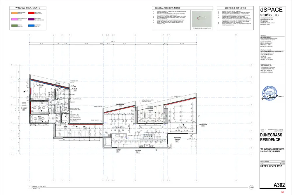
Text of page 55
GENERAL FIRE DEPT. NOTES
WINDOW TREATMENTS 1.
MOTORIZED SOLAR SHADES
MANUAL SOLAR SHADES
PROVIDE A COMPLETE TYPE NFPA 13D FIRE SPRINKLER SYSTEM FOR THE ENTIRE HOUSE. PROVIDE FULLY MONITERED FIRE ALARM SYSTEM TO COMPLY WITH SAUGATUK FIRE DEPT REQUIREMENTS. PROVIDE 2-1/2" FIRE DEPARTMENT CONNECTION ON THE HOUSE ALL FIRESPRINKLERS TO BE CONCEALED, FLANGE - STYLE PER THE ADJACENT IMAGE ALL SPRINKLER PIPES TO RUN WITHIN CEILING, NO EXPOSED PIPING AND NO ADDITIONAL SOFFITS WILL BE PERMITTED. REFER TO RCPS SHEETS AND PLUMBING DRAWINGS FOR ADDITIONAL INFO
2. 3. 5.
MANUAL BLACKOUT SHADES
MOTORIZED BLACKOUT SHADES
6. 7.
MANUAL DRAPERY
LIGHTING & RCP NOTES 1. 2. 3. 4. 5.
6. 7.
MOTORIZED DRAPERY
dSPACE
REF A703 FOR LIGHT FIXTURE SCHEDULES. PROVIDE BUDGET ALLOWANCE FOR ALL LANDSCAPE LIGHTING. REF ELECTRICAL DWGS FOR ADDITIONAL ELECTRICAL INFO. GC & EC TO COORDINATE LIGHT FIXTURES WITH MECHANICAL , PLUMBING & RELATED EQUIPMENT IN THE CEILING. THE ELECTRICAL CONTRACTOR SHALL SPRAY PAINT FULL DOWNLIGHT FIXTURE LAYOUT ON CEILING OR FLOOR & IDENTIFY ANY CONFLICTS IN THE FIELD FOR COORDINATION & REVIEW W/ THE ARCHITECT & CLIENT ON SITE, PRIOR TO INSTALLATION. NO ADDITIONAL SOFFITS WILL BE PERMITTED. REFER TO ELECTRICAL SHEETS AND INTERIOR ELEVATIONS FOR RECEPTACLE LOCATIONS
studio LTD www.dspacestudio.com info@dspacestudio.com 773.423.2920 2920 North Lincoln Avenue Chicago, IL 60657
TYPICAL CONCEALED SPRINKLER HEAD
5.1
5.4
7.2
ARCHITECT
dSPACE STUDIO LTD KEVIN TOUKOUMIDIS, BOB MCFADDEN, JOSEPH KAFTAN, LILLIAN JONES, & HAYLEY BURROUGHS
109' - 11" 15' - 10"
5' - 6"
5' - 0"
21' - 11"
4 1/2"
6' - 5"
14' - 6"
18' - 6"
2' - 7"
2920 N LINCOLN AVE CHICAGO, IL 60657 PHONE: 773.423.2920
19' - 3 1/2"
STRUCTURAL ENGINEER
GOODFRIEND MAGRUDER STRUCTURE, LLC BOB MAGRUDER & ERIC WHITE
53 W. JACKSON BLVD. SUITE 340 CHICAGO, IL 60604 PHONE: 312.607.9898
GENERAL CONTRACTOR
ZAHN BUILDERS, INC TONY ZAHN & MATT BRUURSEMA
9' - 0"
443 DOUGLAS AVE #40 HOLLAND, MI 49424 PHONE: 616.738.9246
EQ EQ
2' - 6"
2' - 0"
SHADE COVE,TYP
F6 Z41
F6 Z41
F28 Z40
F6 Z41
F6 Z41
EQ
PWDR 205
8' - 6" F1 Z37
F1 Z37
F1 Z36
F1 Z35
HALL 206
F1 Z37
F1 Z36
F1 Z36
EQ 2' - 6" 1' - 3" 1' - 3" 2' - 6"
F1 Z37
F1 Z39
F1 Z38
F6 Z58 3' - 6 3/8" 1' - 9" EQ
F6 Z58 EQ 1' - 9" 3' - 6 3/8"
F1 Z39
F1 F1 Z39 Z39 WALL
KP
SD CO
EQ
EQ
EQ
7' - 0"
F1 Z43
F1 Z56 F1 Z56 1' - 11"
7' - 3"
F1 Z55
F1 Z54
F1 Z55
F1 Z54
7' - 3"
F FP
2' - 0"
F6 Z44
F6 Z44
EQ
3' - 2"
3' - 4"
6' - 2"
F1 Z47
F1 Z47
F6 Z44
3' - 4"
F1 Z47
3' - 4"
F1 Z47
3' - 4"
3' - 4"
F1 Z47
F1 Z47 F6 F6 Z48 Z48
K 4' - 0"
PANTRY 212
KITCHEN 211
3' - 4"
3' - 4"
F1 Z47 HOOD-1
F1 Z47
2' - 8"
F1 Z43 F29 Z45
F6 Z44
3' - 3"
F8 F8 F8 F8 Z46 Z46 Z46 Z46
F6 Z44
9' - 6"
KP
F1 Z43
11"
2' - 0"
ISLAND F21 Z50
7' - 0"
KP
3' - 3"
F1 Z37
Z1
5' - 2 1/2"
F40 Z82
F1 Z54
KP
F1 Z37
F15 Z59
F1 Z55
EQ ISL
3' - 4"
F1 Z47
F1 Z47
2' - 8" F1 Z52
F1 Z53
01.13.25
EQ
F6 F6 Z48 Z48
WOODLAND TERRACE 210
F40 Z57
F21 Z49
SHADE & DRAPE SCOPE UPDATES
07.08.25
ISSUE FOR PERMIT
DUNEGRASS RESIDENCE
F40 Z57
SKYLIGHT, REF A702 3' - 4"
F1 Z52
LIVING ROOM 209
EQ
EQ
EQ EQ
EQ
F1 Z42 F1 Z42
SKYLIGHT ABOVE SINK
EF-1 ON VERT FACE OF SKYLIGHT WELL
F40 Z82
F1 Z54
4' - 0"
EQ
F12 VERTICAL LED ACCENT AT MIRROR
EQ
3' - 3 1/8"
5' - 2"
2' - 6"
2' - 6"
2' - 6"
2' - 0"
3' - 8"
3' - 0"
F1 Z56
F6 Z58
KP
5' - 0"
F3 Z60
2' - 2"
F6 Z58
F1 Z42
3' - 0"
Z61
F1 Z42
F12 Z65
F3 F26 Z60 Z63 F3 Z60
COVERED OUTDOOR LOUNGE 208
F1 Z54
F1 Z55
SD CO
1' - 6 1/8"
F1 Z60
F12 (Z77) VERTICAL LED ACCENT AT NICHE
EQ
9' - 6"
F2 Z76
EF-1
3' - 0"
MECH 203 F12
SHADE COVE,TYP
HEATER-1
SD CO
OC Z61
3' - 3 1/4"
4' - 10 1/2"
F1 Z66
F12 Z68
F2 Z76
F1 Z78
DINING ROOM 207
EQ
EQ
F12 Z61
EQ
3' - 0"
EQ
6' - 10 1/2"
EQ
DOOR
KP
F21 Z69
F12 Z68 9' - 6"
2' - 9"
INSTALL CEILING HEATERS FLUSH IN EXT SOFFIT
KP
DR F12 Z68
P. CLOSET 202
3' - 0"
F1 F1 Z74 Z74 1' - 10" 3' - 8 1/2" 2' - 5 1/4"
F21 (VERTICAL LED)
2' - 5"
3' - 0"
SKYLIGHT WELL
3' - 1"
2' - 9"
SHADE COVE,TYP
EF-2 F1 ON VERT FACE OF Z75
2' - 5"
F21 Z69
F32 (Z72) READING SCONCES
F21 Z79 KP
VANITY
KP
F1 Z66
SKYLIGHT
1' - 6"1' - 6" F31 Z71
LED UPLIGHT AT HEADBOARD
(2)F8 Z80 F1 Z75
HEATER-1
DR F31 Z71
F1 Z70
KP
5' - 0 1/2"
58' - 6"
2' - 5 1/2"
5' - 1 1/2"
2' - 5"
P. BATH 201
F1 Z75
F1 Z67 F1 Z67 F1 Z67 KP
2' - 5"
9' - 6"
10' - 6"
F1 Z70
10' - 6"
BED
KP
10' - 4 1/2"
9' - 6"
1' - 8"
F1 Z73
SHADE & DRAPERY COVE,TYP
10' - 6"
1' - 6"
EQ
F21 Z81
EQ
Z1
1' - 10"
195 DUNEGRASS RIDGE DR SAUGATUCK, MI 49453
PROJECT NUMBER: SCALE:
0244.01 AS NOTED
UPPER LEVEL RCP
2 UPPER LEVEL RCP 3/16" = 1'-0"
5.1
5.4
7.2
TRU
RTH E NO
A302 55
Page 56
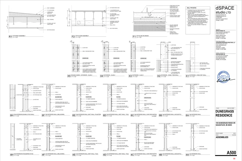
Text of page 56
1 1/2"
1/4" COVER BOARD
1-1/2" GYPCRETE W/ 2X4 SLEEPERS & RADIANT TUBING
TAPERED RIGID INSULATION
1' - 2"
REINFORCING, REF STRUCT DWGS HYDRONIC RADIANT TUBING SYSTEM, REF MECH DWGS
CONC SLAB PER STRUCT
SUSPENDED T-BAR GRID TO SUPPORT DRYWALL CEILING INSUL-2 (R-23)
6 MIL POLY MOISTURE BARRIER: EXTEND TO FOOTINGS, TYP
14" WOOD I-JOIST, REF STRUCT DWGS
STRUCT SAWCUT JOINT, FILL JOINT W/ SILICONE CAULK (MAPEI MASESIL T)
1/8"
14" WOOD I-JOIST, REF STRUCT DWGS
11 1/2"
INSUL-1 (R60 MIN)
1' - 2"
3/4" STRUCTURAL PLYWOOD SUBFLOORING, REF STRUCT
2' - 3"
3/4" PLYWD SHEATHING, REF STRUCT DWGS
PER STRUCT
3/4" SCHED WOOD FLOOR
ROOF-1 MEMBRANE
SCHED FINISH, REF FINISH FLOOR PLAN (A111) & FINISH SCHED (A700)
5/8" GYP BD CEILING
WALL TYPE NOTES 1. COORDINATE FINAL WALL FINISH W/ INTERIOR ELEVATIONS & FINISH SCHEDULE, TYP 2. ALL WALL ASSEMBLIES TO COMPLY WITH LOCAL BUILDING CODES 3. VERIFY ALL TILLE / MILLWORK ASSEMBLIES AND INSTALLATION METHODS W/ MANUFACTURER PRIOR TO INSTALLATION, COORD ANY DISCREPANCIES W/ ARCHITECT 4. AT ALL BATHROOMS AND LAUNDRY ROOMS: PROVIDE 5/8" TYPE "X" MOISTURE RESISTANT GYP BD IN LIEU OF STANDARD GYP BD ON ALL WALLS AND CEILINGS 5. AT ALL SHOWERS & WET APPLICATIONS: PROVIDE 1/2" CEMENT BOARD W/ CONTINOUS WATERPROOFINGAS SPECIFIED, REF FINSIH SCHEDULE (A700) 6. AT ALL TILE LOCATIONS: PROVIDE 1/2" CEMENT BD BACKER
RIGID INSULATION BOARD (R10 MIN)
5/8" GYP BD CEILING
R1
F2
TYP FLOOR ASSEMBLY 1" = 1'-0"
F1
3/8" 2 5/8"
3/8" 2 5/8"
3/8" 3/4"
VARIES
studio LTD www.dspacestudio.com info@dspacestudio.com 773.423.2920 2920 North Lincoln Avenue Chicago, IL 60657
ARCHITECT
dSPACE STUDIO LTD
GRANULAR FILL (COARSE GRAVEL), REF GEOTECH REPORT
TYP ROOF ASSEMBLY 1" = 1'-0"
dSPACE
KEVIN TOUKOUMIDIS, BOB MCFADDEN, JOSEPH KAFTAN, LILLIAN JONES, & HAYLEY BURROUGHS
2920 N LINCOLN AVE CHICAGO, IL 60657 PHONE: 773.423.2920
TYP SLAB ON GRADE 3" = 1'-0"
VARIES
REF STRUCT
STRUCTURAL ENGINEER
REF STRUCT
VARIES
GOODFRIEND MAGRUDER STRUCTURE, LLC BOB MAGRUDER & ERIC WHITE
1" 2x WD STUDS
2x WD STUDS
2x WD STUDS
INSUL-1 (R30 MIN) SPRAY FOAM
1" GAP (MIN) BETWEEN CONC WALL & WD STUDS, TYP
5/8" GYP BD
5/8" GYP BD
5/8" GYP BD
INSUL-1 (R30 MIN) SPRAY FOAM
INSUL-1 (R30 MIN) SPRAY FOAM
53 W. JACKSON BLVD. SUITE 340 CHICAGO, IL 60604 PHONE: 312.607.9898
2x WD STUDS
INSUL-1 (R19 MIN) SPRAY FOAM
GENERAL CONTRACTOR
PROVIDE CLEAR MATTE SEALER FOR ABOVE GROUND WALLS
X5
UNDERSIDE OF STRUCTURE
9 1/4"
SCHED CEILING
INTERIOR SIDE
3/4" PLYWOOD SHEATHING, REF STRUCT DWGS
3/4" PLYWOOD SHEATHING, REF STRUCT DWGS
EXTERIOR BUILDING AIR / WATER BARRIER (WP-1)
EXTERIOR BUILDING AIR / WATER BARRIER (WP-1)
EXTERIOR BUILDING AIR & WATER BARRIER (WP-1)
CLAD-2: RENSEN LINARTE ALUMINUM FIN CLADDING SYSTEM ON RENSEN HORIZONTAL CLIP SYSTEM ON 3/8" DUPONT RAINVENT FURRING STRIPS
CLAD-2: RENSEN LINARTE ALUMINUM FIN CLADDING SYSTEM ON RENSEN HORIZONTAL CLIP SYSTEM ON 3/8" DUPONT RAINVENT FURRING STRIPS
CLAD-1: 3/4" TONGUE & GROOVE WOOD SIDING OVER 3/8" DUPONT RAINVENT FURRING STRIPS
DOUBLE SIDED - EXTERIOR - CLAD-2 1" = 1'-0"
X4
EXTERIOR - CLAD-2 1" = 1'-0"
DRAINAGE BOARD
DRAINAGE BOARD 2" RIGID INSULATION BOARD (R-10 MINIMUM)
2" RIGID INSULATION BOARD (R-10 MINIMUM) 1" GAP BETWEEN CONC WALL & WD STUDS, TYP
X3
EXTERIOR - CLAD-1 1" = 1'-0"
X2
EXTERIOR - CONC / FND WALL 1" = 1'-0"
X1
EXTERIOR - CONC RET WALL 1" = 1'-0"
UNDERSIDE OF STRUCTURE
5 1/2"
UNDERSIDE OF STRUCTURE
5 1/2"
UNDERSIDE OF STRUCTURE
5 1/2"
UNDERSIDE OF STRUCTURE
5 1/2"
SCHED CEILING
6 7/8"
SCHED CEILING
7 1/4"
SCHED CEILING
6 3/4"
SCHED CEILING
6 3/4"
SCHED CEILING
6 3/4"
SCHED CEILING
5/8" GYP BD
5/8" GYP BD
INSUL-2
2X6 WD STUDS
2X6 WD STUDS
2X6 WD STUDS
INSUL-2
INSUL-2
MILLWORK SIDE
PLASTER SIDE
TILE SIDE
SCHED SUBSTRATE
1/2" CEMENT BACKER BD
1/2" CEMENT BACKER BD
CRACK ISOLATION MEMBRANE
CRACK ISOLATION MEMBRANE
PLASTER (MICROCEMENT), REF INT ELEVS AND FINISH SCHED (A700)
1/4" THIN-SET MORTAR
FIRE STOP AT 2X6'S HORIZONTALLY 1 LAYER 5/8" TYPE "X" GYP EACH SIDE
SCHED FLOOR FINISH
2x6 INTERIOR WALL (MILLWORK)
6F 1" = 1'-0"
5/8" GYP BD EACH SIDE
2X6 WD STUDS
2X6 WD STUDS
INSUL-2
SCHED BASE
3/8" TILE, REF INT ELEVS AND FINISH SCHED (A700) FOR FINISH
SCHED FLOOR FINISH
SCHED FLOOR FINISH
INSUL-2 2X6 16" OC WD STUDS, EFFECTIVELY FIRE STOPPED AT 2X6'S
SCHED BASE SCHED FLOOR FINISH
5/8" GYP BD EACH SIDE
FIRE-RATED SIDE
SCHED BASE DETAIL, REF INT ELEVATIONS
2X4 WD BASE PLATE
6 3/4"
FLUID-APPLIED WATERPROOFING MEMBRANE (WP-3)
5 1/2"
SCHED MILLWORK FINISH, REF INT ELEVATIONS AND FINISH SCHED (A700)
5 1/2"
CAST-IN-PLACE CONC WALL, REF STRUCT DWGS
UNDERSIDE OF STRUCTURE
2X4 WD STUDS
2X4 INTERIOR DOUBLE STUD WALL
CAST-IN-PLACE CONCRETE, REF STRUCT DRAWING
3/4" PLYWOOD SUBSTRATE, REF STRUCT
5 1/2"
5/8" GYP BD EACH SIDE
8H 1" = 1'-0"
INTERIOR SIDE
INTERIOR SIDE
UNDERSIDE OF STRUCTURE
INSUL-2 (BOTH SIDES)
PLAN DIAGRAM
443 DOUGLAS AVE #40 HOLLAND, MI 49424 PHONE: 616.738.9246
7 1/8"
(2) 2X4 WD TOP PLATE
2X4 WD STUDS
INTERIOR SIDE
ZAHN BUILDERS, INC TONY ZAHN & MATT BRUURSEMA
2x6 INTERIOR WALL (WET WALL: PLASTER)
6E 1" = 1'-0"
2x6 INTERIOR WALL (WET WALL: TILE)
6D 1" = 1'-0"
SCHED BASE
SCHED BASE
SCHED FLOOR FINISH
SCHED FLOOR FINISH
2x6 INTERIOR WALL (1HR FIRE RATED) UL #U305
6C 1" = 1'-0"
2x6 INTERIOR WALL (ACOUSTIC)
6B 1" = 1'-0"
SCHED BASE 07.08.25
2x6 INTERIOR WALL
6A 1" = 1'-0"
UNDERSIDE OF STRUCTURE
5 1/8"
UNDERSIDE OF STRUCTURE
3 1/2"
UNDERSIDE OF STRUCTURE
3 1/2"
UNDERSIDE OF STRUCTURE
3 1/2"
UNDERSIDE OF STRUCTURE
3 1/2"
UNDERSIDE OF STRUCTURE
3 1/2"
UNDERSIDE OF STRUCTURE
SCHED CEILING
3 1/2"
SCHED CEILING
4 7/8"
SCHED CEILING
5 1/4"
SCHED CEILING
4 3/4"
SCHED CEILING
4 3/4"
SCHED CEILING
4 3/4"
SCHED CEILING
(2) 2X6 WD TOP PLATE INSUL-2
INSUL-2 5/8" GYP BD EACH SIDE
5/8" GYP BD
5/8" GYP BD
FIRE STOP AT 2X4'S HORIZONTALLY
2X4 WD STUDS
2X4 WD STUDS
1 LAYER 5/8" TYPE "X" GYP EACH SIDE 2X4 16" OC WD STUDS, EFFECTIVELY FIRE STOPPED AT 2X4'S
2X4 WD STUDS
INSUL-2
INSUL-2
MILLWORK SIDE
PLASTER SIDE
TILE SIDE
SCHED SUBSTRATE
1/2" CEMENT BACKER BD
1/2" CEMENT BACKER BD
CRACK ISOLATION MEMBRANE
CRACK ISOLATION MEMBRANE
PLASTER (MICROCEMENT), REF INT ELEVS AND FINISH SCHED (A700)
1/4" THIN-SET MORTAR
5/8" GYP BD EACH SIDE
STAGGERED 2X4 WD STUDS
SCHED BASE DETAIL, REF INT ELEVATIONS
2X6 WD BASE PLATE
SCHED BASE SCHED FLOOR FINISH
SCHED FLOOR FINISH
2X4 INTERIOR STAGGERED STUD
4H 1" = 1'-0"
195 DUNEGRASS RIDGE DR SAUGATUCK, MI 49453
2X4 WD STUDS
2X4 WD STUDS
INSUL-2
0244.01
PROJECT NUMBER: SCALE:
AS NOTED
ASSEMBLIES
INSUL-2
SCHED MILLWORK FINISH, REF INT ELEVATIONS AND FINISH SCHED (A700)
PLAN DIAGRAM
DUNEGRASS RESIDENCE
5/8" GYP BD EACH SIDE
FIRE-RATED SIDE STAGGERED 2X4 WD STUDS
ISSUE FOR PERMIT
SCHED FLOOR FINISH
2x4 INTERIOR WALL (MILLWORK)
4F 1" = 1'-0"
SCHED BASE
3/8" TILE, REF INT ELEVS AND FINISH SCHED (A700) FOR FINISH
SCHED BASE
SCHED BASE
SCHED FLOOR FINISH
SCHED FLOOR FINISH
SCHED FLOOR FINISH
SCHED FLOOR FINISH
2x4 INTERIOR WALL (WET WALL: TILE)
4E 1" = 1'-0"
REF INT ELEVS AND FINISH SCHED (A700) FOR FINISH
2x4 INTERIOR WALL (WET WALL: TILE)
4D 1" = 1'-0"
2x4 INTERIOR WALL (1HR FIRE RATED)
4C 1" = 1'-0"
UL #U305
2x4 INTERIOR WALL (ACOUSTIC)
4B 1" = 1'-0"
SCHED BASE SCHED FLOOR FINISH
2x4 INTERIOR WALL
4A 1" = 1'-0"
A500 56
Page 57
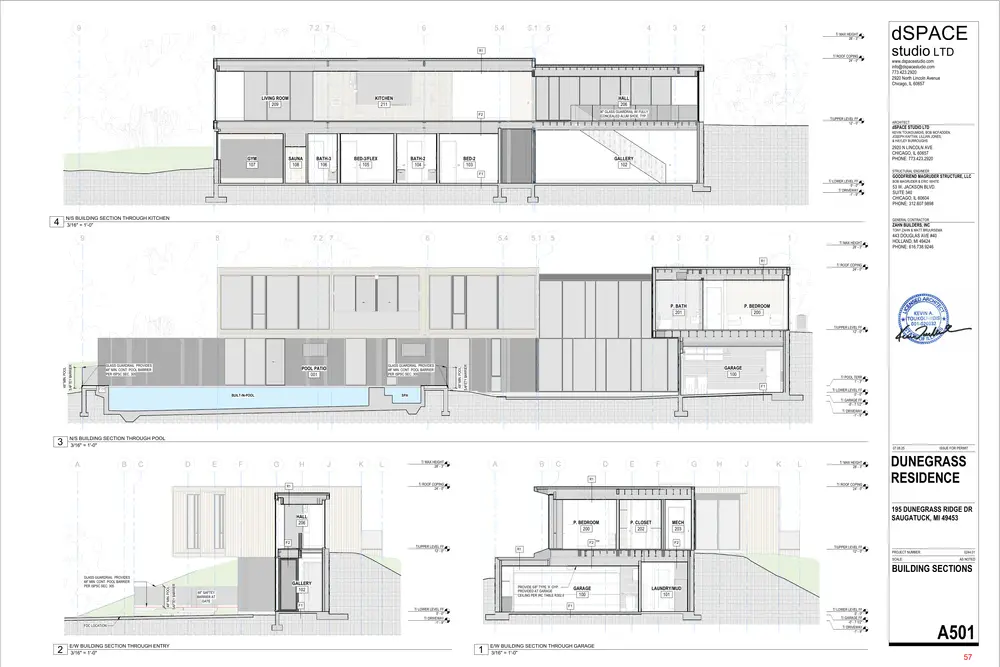
Text of page 57
7.2 7
5.4
5.1
1 T/ MAX HEIGHT 28' - 3"
R1 T/ ROOF COPING 24' - 0"
LIVING ROOM 209
KITCHEN 211
dSPACE studio LTD www.dspacestudio.com info@dspacestudio.com 773.423.2920 2920 North Lincoln Avenue Chicago, IL 60657
HALL 206 36" GLASS GUARDRAIL W/ FULLY CONCEALED ALUM SHOE, TYP.
F2
T/UPPER LEVEL FF 12' - 0"
ARCHITECT
dSPACE STUDIO LTD KEVIN TOUKOUMIDIS, BOB MCFADDEN, JOSEPH KAFTAN, LILLIAN JONES, & HAYLEY BURROUGHS
GYM 107
SAUNA 108
BATH-3 106
BED-3/FLEX 105
BATH-2 104
BED-2 103
2920 N LINCOLN AVE CHICAGO, IL 60657 PHONE: 773.423.2920
GALLERY 102
STRUCTURAL ENGINEER
F1
GOODFRIEND MAGRUDER STRUCTURE, LLC T/ LOWER LEVEL FF 0' - 0" T/ DRIVEWAY -1' - 9"
N/S BUILDING SECTION THROUGH KITCHEN 3/16" = 1'-0"
BOB MAGRUDER & ERIC WHITE
53 W. JACKSON BLVD. SUITE 340 CHICAGO, IL 60604 PHONE: 312.607.9898 GENERAL CONTRACTOR
ZAHN BUILDERS, INC TONY ZAHN & MATT BRUURSEMA
7.2 7
5.4
5.1
T/ MAX HEIGHT 28' - 3"
443 DOUGLAS AVE #40 HOLLAND, MI 49424 PHONE: 616.738.9246
R1 T/ ROOF COPING 24' - 0"
P. BATH 201
P. BEDROOM 200
BUILT-IN-POOL
SAFETY BARRIER
GLASS GUARDRAIL PROVIDES 48" MIN. CONT. POOL BARRIER PER ISPSC SEC. 305
POOL PATIO 001
48" MIN. POOL
GLASS GUARDRAIL PROVIDES 48" MIN. CONT. POOL BARRIER PER ISPSC SEC. 305
SAFTEY BARRIER
48" MIN. POOL
T/UPPER LEVEL FF 12' - 0"
GARAGE 100
T/ POOL TERR 1' - 3"
F1
T/ LOWER LEVEL FF 0' - 0"
SPA
T/ GARAGE FF -0' - 7 1/2" T/ DRIVEWAY -1' - 9"
N/S BUILDING SECTION THROUGH POOL 3/16" = 1'-0"
07.08.25
T/ MAX HEIGHT 28' - 3"
T/ MAX HEIGHT 28' - 3"
R1 T/ ROOF COPING 24' - 0"
R1
T/ ROOF COPING 24' - 0"
HALL 206
P. BEDROOM 200
F2
F2 T/UPPER LEVEL FF 12' - 0"
SIM
P. CLOSET 202
ISSUE FOR PERMIT
DUNEGRASS RESIDENCE 195 DUNEGRASS RIDGE DR SAUGATUCK, MI 49453
MECH 203 F2 T/UPPER LEVEL FF 12' - 0"
R1
PROJECT NUMBER: SCALE:
0244.01 AS NOTED
FDC LOCATION
E/W BUILDING SECTION THROUGH ENTRY 3/16" = 1'-0"
SAFTEY BARRIER
GLASS GUARDRAIL PROVIDES 48" MIN. CONT. POOL BARRIER PER ISPSC SEC. 305
48" MIN. POOL
BUILDING SECTIONS 48" SAFTEY BARRIER AT GATE
GALLERY 102
PROVIDE 5/8" TYPE ‘X’ GYP. PROVIDED AT GARAGE CEILING PER IRC TABLE R302.6
F1
GARAGE 100 F1
T/ LOWER LEVEL FF 0' - 0" T/ DRIVEWAY -1' - 9"
E/W BUILDING SECTION THROUGH GARAGE 3/16" = 1'-0"
LAUNDRY/MUD 101 T/ LOWER LEVEL FF 0' - 0" T/ GARAGE FF -0' - 7 1/2" T/ DRIVEWAY -1' - 9"
A501 57
Page 58
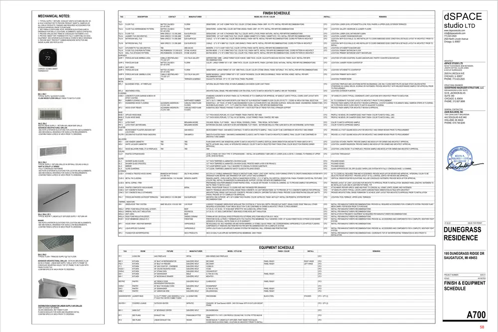
Text of page 58
MECHANICAL NOTES: 1. TYPICAL SUPPLY / RETURN / EXHAUST VENTS OUTLINED BELOW. GC & HVAC CONTRACTOR TO PROVIDE PRODUCT SHEET & SAMPLES OF ALL GRILLE PRODUCTS, FINISHES AND REQUIRED ACCESSORIES FOR REVIEW & APPROVAL PRIOR TO PURCHASE. 2. SEE FINISH FLOOR PLANS, RCPS, INTERIOR ELEVATIONS & MECH DRAWINGS FOR GRILLE LOCATIONS, ALIGNMENTS, SIZES & CFM NOTES. 3. PROVIDE GRILLES AND TRIMS W/ CONCEALED FASTENERS U.N.O. 4. PROVIDE 'SMART' WIFI THERMOSTATS FULLY COMPATIBLE W/ HVAC EQUIPMENT, SEE INTERIOR ELEVATIONS & COORD W/ MECH DRAWINGS 5. PROVIDE NEST "PROTECT" CARBON MONOXIDE DETECTOR AND SMOKE ALARM, SEE RCPS & A703
FINISH SCHEDULE TAG
DESCRIPTION
TILE TILE-1
FLOOR TILE
TILE-2
FLOOR TILE (HERRINGBONE PATTERN)
TILE-3 TILE-4 TILE-5 TILE-6
CONTACT
CFCI
LOCATION: LOWER LEVEL KITCHENETTE & GYM, POOL PAVERS, & UPPER LEVEL EXTERIOR TERRACES
FLORIM
SENSITERRE - (SIZING TBD), COLOR: MATTONE GRANA, FINISH: GRIP - R11 PTV. INSTALL PER MFR RECOMMENDATIONS
CFCI
LOCATION: GALLERY, MUDROOM, & LAUNDRY FLOORS
FLOOR TILE LAUNDRY TILE (DECORATIVE) BATHROOM WALL TILE
ELM SURFACES FLORIM ELM SURFACES
SENSAZIONE - 24" X 48" X (THICKNESS TBD) TILE, COLOR: WHITE LITHOS, FINISH: NATURAL. INSTALL PER MFR RECOMMENDATIONS SENSITERRE - 24" X 48" X 9MM THICK TILE, COLOR: SABBIA CANNETTATO, FINISH: CANNETTATO - R10. INSTALL PER MFR RECOMMENDATIONS CASALE - 12" X 18" X 9MM TILE. COLOR: BRUSH BIANCO, FINISH: MATTE. INSTALL PER MFR RECOMMENDATIONS. COORD PATTERN W/ ARCHITECT
CFCI CFCI CFCI
BATHROOM WALL TILE
NIKKI GRIECO / 312.506.2880
ELM SURFACES
CASALE - 12" X 18" X 9MM TILE. COLOR: LINES BIANCO, FINISH: MATTE. INSTALL PER MFR RECOMMENDATIONS. COORD PATTERN W/ ARCHITECT
CFCI
TILE-7 KITCHENETTE TILE (DECORATIVE) TILE-8 FLOOR TILE (CHEVRON PATTERN) TILE-9 WALL TILE (STACKED PATTERN) SURFACES SURF-1 PORCELAIN SLAB (MARBLE-LOOK)
TBD IRIS ROBINSON / 312.909.6215 IRIS ROBINSON / 312.909.6215
ANN SACKS STONE SOURCE STONE SOURCE
MODERN - 3" X 9" X 0.649" THICK TILE, COLOR: COTTON, FINISH: MATTE. INSTALL PER MFR RECOMMENDATIONS MUTINA MEWS - 2" X 16" X 9MM THICK TILE, COLOR: FOG, FINISH: MATTE. INSTALL PER MFR RECOMMENDATIONS. COORD PATTERN W/ ARCHITECT MUTINA MEWS - 2" X 16" X 9MM THICK TILE, COLOR: FOG, FINISH: MATTE. INSTALL PER MFR RECOMMENDATIONS. COORD PATTERN W/ ARCHITECT
CFCI CFCI
LOCATION: LOWER LEVEL BATHROOM FLOORS LOCATION: LAUNDRY ROOM BACKSPLASH LOCATION: BATH 02-03 WALLS. GC AND INSTALLER TO COORD EMBOSSED EDGE CONDITION & DETAILED LAYOUT W/ ARCHITECT PRIOR TO INSTALL LOCATION: BATH 02-03 WALLS.GC AND INSTALLER TO COORD EMBOSSED EDGE CONDITION & DETAILED LAYOUT W/ ARCHITECT PRIOR TO INSTALL LOCATION: KITCHENETTE BACKSPLASH LOCATION: PRIMARY BATHROOM FLOOR LOCATION: PRIMARY BATHROOM VANITY BACKSPLASH
CAMILLE WESTMOLAND / 773.339.1277 MATTEO CALISESI / 931.401.6764
ICG ITALIA GALLERY
SAPIENSTONE 12MM – LARGE FORMAT 63CM X126CM, 12MM THICK, COLOR: CALACATTA MACCHIA VECCHIA, FINISH: SILKY. INSTALL PER MFR RECOMMENDATIONS. COLOR - LARGE FORMAT 63" X 126", 12MM THICK, COLOR: COLOR WHITE, FINISH: LEATHER, EDGE: NATURAL. INSTALL PER MFR RECOMMENDATIONS
CFCI
LOCATION: KITCHEN COUNTERS, ISLAND & BACKSPLASH, PANTRY COUNTER & BACKSPLASH
CFCI
LOCATION: LAUNDRY ROOM COUNTERTOP
MATTEO CALISESI / 931.401.6764 CAMILLE WESTMOLAND / 773.339.1277 TBD
FLORIM
SENSITERRE - LARGE FORMAT 45" X 95", 6MM THICK, COLOR: COLOR COTONE GRANA, FINISH: NATURALE - R10, INSTALL PER MFR RECOMMENDATIONS
CFCI
LOCATION: KITCHENETTE COUNTERTOP
ICG ITALIA GALLERY
MARMI MAXIMUN - LARGE FORMAT 60" X 120", 0,60CM THICKNESS, COLOR: BRECCIA MIRABILE, FINISH: NATURAL HONED. INSTALL PER MFR RECOMMENDATIONS CALACATTA VINTAGE - 57" X 115", 2CM THICK, FINISH: POLISHED
CFCI
LOCATION: PRIMARY BATH VANITY
NATURAL MILLED FINISH STEEL W/ NON-FLAMMABLE LOW-SHEEN CLEAR COAT FINISH
CFCI
SURF-3 (NOT USED) SURF-4 PORCELAIN SLAB
MTL-2 WEATHERED STEEL FLOORING CONC-1 CONCRETE FLOOR (GARAGE & MECH) W/ EPOXY COATING RB-1 RUBBER FLOORING (GYM) WF-1 ENGINEERED WOOD FLOORING WF-2
WOOD STAIR TREADS
WD-3 WOOD MILLWORK PANEL (TV & FIREPLACE) CEILING CLG-1 PAINTED GYPSUM BOARD GLASS GL-1 SHOWER GLASS (CLEAR) GL-2 SHOWER GLASS (FROSTED) GL-3 MIRROR GL-4 GLASS GUARDRAIL EXTERIOR CLAD-1 STAINED & TREATED WOOD SIDING
FLORIM
TERRAZZO & MARBLE
ALEXANDRA ANDERSON / 312.810.1406 ALEXANDRA ANDERSON / 312.810.1406
NORTHWEST RUBBER CARLISLE WIDE PLANK FLOORS CARLISLE WIDE PLANK FLOORS
SA-4 / RA-4 / EF-1 TYPICAL MUD-IN 1" LINEAR SLOT DIFFUSER SUPPLY / RETURN AIR INVIAIR -SEE RCPS & INTERIOR ELEVATIONS FOR LOCATION AND ALIGNMENTS. -SEE MECHANICAL DRAWINGS FOR SIZES & CFM REQUIREMENTS. -CONFIRM FINISH & SPECS W/ ARCH PRIOR TO ORDERING
2920 N LINCOLN AVE CHICAGO, IL 60657 PHONE: 773.423.2920
LOCATION: FIREPLACE AND LOCATIONS NOTED ON DRAWINGS. USE ONLY CLEAN SHEET/PLATE (NO BAR STOCK UNLESS NOTED OTHERWISE) NO VISIBLE WELDS, SCORING OR FASTENERS. PROVIDE ARCHITECT WITH WELDED/FINISHED SAMPLE FOR APPROVAL PRIOR TO PROCUREMENT. LOCATION: EXTERIOR PLANTERS 1/8" SAWCUTS JOINTS TYPICAL; COORDINATE JOINT LOCATIONS WITH ARCHITECT PRIOR TO EXECUTION. GC TO COORDINATE TILE/JOINT LAYOUT W/ ARCHITECT PRIOR TO PROCUREMENT. PROVIDE FINISH SAMPLE FOR ARCHITECT REVIEW & APPROVAL. LOCATE FLOORING TO ELIMINATE SMALL NARROW STRIPS OF FLOORING. GC TO PROVDIE WOOD FLOOR VENTS TO MATCH ADJACENT FLOORING. PROVIDE FINISH SAMPLE FOR ARCHITECT REIVEW & APPROVAL.
PROFILE: NO BEVEL OR CHAMFER EDGE; PAINT FINISH: COLOR TO MATCH WALL, UNO. PROFILE: NO BEVEL OR CHAMFER EDGE; PAINT FINISH: COLOR TO MATCH WALL, UNO.
BENJAMIN MOORE BENJAMIN MOORE
CEILINGS: REGAL, FLAT FINISH, WALLS: REGAL, EGGSHELL FINISH, TRIM: REGAL, SATIN FINISH BATHROOM CEILINGS: AURA BATH & SPA WATERBORNE, FLAT FINISH, BATHROOM WALLS & TRIM: AURA BATH & SPA WATERBORNE, SATIN FINISH
CFCI CFCI
COLOR TO MATCH APPROVED SAMPLE COLOR TO MATCH APPROVED SAMPLE
SAN MARCO
MICROCEMENT FINISH - SAN MARCO CONTINUO. TO MATCH ARCHITECTS SAMPLE. FINAL COLOR TO BE CONFIRMED BY ARCHITECT AND OWNER
CFCI
PROVIDE (4) 2 FOOT SQUARE MOCK-UPS FOR ARCHITECT AND OWNER REVIEW PRIOR TO PROCUREMENT
SAN MARCO
SMOOTH PLASTER FINISH - SAN MARCO MARMORINO CLASSICO, MATTE FINISH TO MATCH ARCHITECTS SAMPLE, FINAL COLOR TO BE CONFIRMED BY ARCHITECT AND OWNER
CFCI
PROVIDE (4) 2 FOOT SQUARE MOCK-UPS FOR ARCHITECT AND OWNER REVIEW PRIOR TO PROCUREMENT
TBD TBD
TBD TBD
CFCI CFCI
LOCATION: KITCHEN, PANTRY. PROVIDE SAMPLE AND MOCK-UP FOR OWNER AND ARCHITECT APPROVAL. LOCATION: LAUNDRY/MUDROOM. PROVIDE SAMPLE AND MOCK-UP FOR OWNER AND ARCHITECT APPROVAL.
TBD
TBD
PLAIN SAWN WHITE OAK VENEER MILLWORK TO MATCH ARCHITECT'S SAMPLE VERTICAL GRAIN ORIENTATION AND MATTE FINISH (MATCH WF-1) MATTE LACQUER, WALL HUNG, W/ INTEGRATED HANDLES, COLOR TO MATCH SELECTED PAINT FINISH (FINAL COLOR SELECTION PENDING OWNER APPROVAL) TBD
CFCI
LOCATION: LIVING ROOM / TV & FIREPLACE. PROVIDE SAMPLE AND MOCK-UP FOR OWNER AND ARCHITECT APPROVAL.
LEVEL 5 FINISH, 5/8" THICK TYPE 'X' GYPSUM BOARD -- INSTALL ON SUSPENDED T-BAR GRID AT LOWER LEVEL & ON RC-1 CHANNEL TO FRAMING AT UPPER LEVEL (SHIM AS REQ'D)
CFCI
LOCATION: THROUGHOUT
1/2" THICK TEMPERED & LAMINATED LOW-IRON GLASS 1/2" THICK TEMPERED & LAMINATED LOW-IRON GLASS, FROSTED INNER LAYER (FOR PRIVACY) 1/4" CLEAR MIRROR GLASS - FULLY ADHERED TO CONCEAL PLYWOOD SUBSTRATE 1/2" CLEAR, TEMPERED LAMINATED SAFETY GLASS W/ POLISHED EDGES
CFCI CFCI CFCI CFCI
POLISHED EDGES POLISHED EDGES POLISHED EDGES GLASS SUPPORTED BY CRL DRY-GLAZED TAPER-LOCK SYSTEM WITH FULLY CONCEALED SHOE / U-CHANNEL
BORAL
THERMAL / MOISTURE GR-1 GREEN ROOF TRAY SYSTEM
KEVIN TOUKOUMIDIS, BOB MCFADDEN, JOSEPH KAFTAN, LILLIAN JONES, & HAYLEY BURROUGHS
CFCI CFCI
CLAD-6 PAINTED COMPOSITE FASCIA BOARD CONC-2 EXT CONCRETE PAVING CONC-3 EXT CONCRETE WALLS (STANDARD) PORCELAIN PAVERS (OUTDOOR TERRACES)
www.dspacestudio.com info@dspacestudio.com 773.423.2920 2920 North Lincoln Avenue Chicago, IL 60657
ARCHITECT
1/2" THICK WOOD (POPLAR), W/ 3-COAT PRIMER. FINISH: PAINTED. REF A600 1/2" THICK WOOD (POPLAR), 7.5" TALL W/ 3/8" REVEAL. 3-COAT PRIMER. FINISH: PAINTED. REF A600
CLAD-4 METAL COPING / TRIM
PAV-1
STANDARD CONCRETE W/ EPOXY FINISH, GC TO PROVIDE UP TO 4 SAMPLES FOR APPROVAL 1/8" SAWCUT JOINTS TYPICAL, COORD JOINT LAYOUT WITH CFCI ARCHITECT. 39.5" X 39.5" X 18MM THICK NWR SPORTFLOOR "REACTIO" SLIP-RESISTANT RUBBER FLOOR COLOR: 675 PUTTY - COORD W/ ARCH FOR FINAL SELECTION CFCI ESSENTIALS - 3/4" THICK x 9" WIDE PLANK ENGINEERED FLOOR. FLATSAWN WHITE OAK, BRUSHED SURFACE, HEIRLOOM GRADE, ENGINEERED, ENDMATCHED, CFCI MICROBEVELED EDGES. *(3 FT - 12 FT LENGTHS) FINISH: PEARL. INSTALL PER MFR RECOMMENDATIONS. ESSENTIALS BOX TREADS, FINISHED TO MATCH WF-1. ROUTE BOTTOM OF TREAD FOR STEEL STRINGER SUPPORT CFCI
studio LTD
STRUCTURAL ENGINEER
GOODFRIEND MAGRUDER STRUCTURE, LLC BOB MAGRUDER & ERIC WHITE
53 W. JACKSON BLVD. SUITE 340 CHICAGO, IL 60604 PHONE: 312.607.9898 GENERAL CONTRACTOR
ZAHN BUILDERS, INC
BRANDON WHITEHEAD / DELTA MILLWORKS 512.385.1812 JURGEN SKODA / 310.746.6069 RENSON LINARTE
CLAD-2 METAL FIN CLADDING
CFCI
dSPACE
dSPACE STUDIO LTD
LOCATION: POWDER ROOM
ARCHITECTURAL GRADE, PRE-WEATHERED COR-TEN STEEL PLATE TO MATCH ARCHITECT'S SAMPLE, MIN 3/8" THICKNESS
BASE BASE-1 APPLIED WOOD BASE BASE-2 FLUSH WOOD BASE PAINT PNT-1 LATEX PAINT PNT-2 LATEX PAINT (BATHROOMS) PLASTER CEM-1 MICROCEMENT PLASTER (INDOORS WET LOCATIONS) PLSTR-1 DECORATIVE PLASTER FINISH (INDOORS) MILLWORK WD-1 OAK VENEER CABINETRY WD-2 WHITE LACQUER CABINETRY
SA-3 / RA-3 TYPICAL SUPPLY / RETURN GRILLES IN DRYWALL CEILING & WALLS: HART & COOLEY LF SERIES: -FULLY CONCEALED FASTENERS -SEE RCPS & INTERIOR ELEVATIONS FOR LOCATION AND ALIGNMENTS. -SEE MECHANICAL DRAWINGS FOR SIZES & CFM REQUIREMENTS. -CONFIRM FINISH & SPECS W/ ARCH PRIOR TO ORDERING
REMARKS
SENSITERRE - 24" X 48" X 20MM THICK TILE, COLOR: COTONE GRANA, FINISH: GRIP - R11 PTV. INSTALL PER MFR RECOMMENDATIONS
SURF-6 MARBLE METAL MTL-1 BLACKENED STEEL - AT FIREPLACE
SA-2 / RA-2 MUD-IN J-BEAD SUPPLY / RETURN AIR LINEAR BAR GRILLE: ADVANCED ARCHITECTURAL GRILLES: -SEE RCPS & INTERIOR ELEVATIONS FOR LOCATION AND ALIGNMENTS. -SEE MECHANICAL DRAWINGS FOR SIZES & CFM REQUIREMENTS. -CONFIRM FINISH & SPECS W/ ARCH PRIOR TO ORDERING
INSTALL
FLORIM
SURF-5 PORCELAIN SLAB (MARBLE-LOOK)
SA-1 / RA-1 TYPICAL SUPPLY @ WOOD FLOORS: -FLUSH WOOD FLOOR GRILLE, FINISH TO MATCH FLOOR
MODEL NO / STLYE / COLOR
MATTEO CALISESI / 931.401.6764 MATTEO CALISESI / 931.401.6764 NIKKI GRIECO / 312.506.2880 NIKKI GRIECO / 312.506.2880 NIKKI GRIECO / 312.506.2880
SURF-2 PORCELAIN SLAB CARRIER: ECOBEE SMART THERMOSTAT
MANUFACTURER
NIKKI GRIECO / 312.506.2880
ELM SURFACES
MIKE SELLECK / 616.935.1981
LIVE ROOF
ACCOYA 5.5" (VISIBLE) BARNWOOD TONGUE & GROOVE PLANK, FINISH: LIGHT IVORY. INSTALL OVER FURRING STRIPS TO CREATE RAINSCREEN SYSTEM WITH CFCI DRAINAGE PLANE BEHIND. SEE DRAWINGS FOR JOINT LAYOUT AND ALIGNMENTS RENSON LINARTE - EVEN 30 METAL PROFILE RAINSCREEN SYSTEM: 1.5" X 1.5" METAL FIN (VERTICAL ORIENTATION, FINISH: POWDER COATED RAL TEXTURED CFCI (COLOR TBD). INSTALL ON ANNODIZED ALUMINUM BLADE SUPPORT SYSTEM, PER MFR RECOMMENDATIONS PREFINISHED HIGH-PERFORMANCE KYNAR PAINTED STEEL. 18 GAUGE OR THICKER, TO AVOID OIL-CANNING. GC TO PROVIDE SAMPLE FOR APPROVAL. CFCI MATTE FINISH TO MATCH CLAD-1 BORAL TRUEXTERIOR TRIM,GC TO COORD SIZE AND THICKNESS PER DRAWINGS CFCI SMOOTH TROWELED ARCHITECTURAL-GRADE FINISH CONCRETE, W/ LIGHT BROOM FINISH. GC TO PROVIDE UP TO 4 CONCRETE SAMPLES FOR APPROVAL CFCI ARCHITECTURAL GRADE CAST-IN-PLACE CONCRETE; PROVIDE A SMOOTH, UNIFORM TEXTURE & FINISH. PROVIDE CLEAR PENETRATING SEALANT (MATTE CFCI FINISH). PROVIDE UP TO 4 SAMPLES FOR APPROVAL. ARIOSTEA CM2 OUTDOOR - 48" X 24" X 20MM THICK PAVERS, COLOR: ASTRA ICE, FINISH: ANTI-SLIP. INSTALL ON PEDESTAL SYSTEM PER MFR CFCI RECOMMENDATIONS LIVEROOF 'STANDARD' GREEN ROOF MODULAR TRAY SYSTEM W/ 4" THCIK SOIL DEPTH. PROVIDE SLIP SHEET, DRAIN COVER, EDGE TRIM & ALL OTHER REQUIRED ACCESSORIES. PLANT MEDIA SELECTION TO BE CONFIRMED W/ OWNER & ARCHITECT PRIOR TO PROCUREMENT. 3.5" (R-23) / 5.5" (R-36) / 10" (R-60) BASF SPRAYTITE 158 CLOSED-CELL SPRAY FOAM. 3.5" (R-15) / 5.5" (R23) COMFORTBATT SEMI-RIGID STONE-WOOL BATT INSULATION
CFCI
INSUL-1 SPRAY FOAM INSULATION (WALL & ROOF) INSUL-2 MINERAL WOOL BATT INSULATION INSUL-3 (NOT USED) INSUL-4 RIGID FOAM INSULATION (ROOF) ROOF-1 ROOF MEMBRANE (SINGLE-PLY)
BASF ROCKWOOL BASF OWENS CORNING FIRESTONE
WP-1
HOUSE WRAP / WEATHER BARRIER
VAPROSHIELD
WP-2
LIQUID-APPLIED FLASHING
VAPROSHIELD
FORMULAR 250 (OR EQUAL) RIGID EXTRUDED POLYSTYRENE (XPS) FOAM INSULATION (R-5 / INCH) FIRESTONE 60 MIL ULTRAPLY THERMOPLASTIC POLYOLEFIN (TPO) MEMBRANE, FULLY ADHERED, OVER 1/4" GLASS-FIEBER FACED GYPSUM COVER BOARD (DENSDECK OR EQUAL). WHITE FINISH W/ 25 YR WARRANTY REVEALSHIELD SA, SELF-ADHERED AIR AND WATER BARRIER, UV STABLE, BLACK FINISH. USE COORESPONDING VAPROSHIELD FLUID-APPLIED FLASHING COMPONENTS AT WINDOWS AND PENETRATION PER MFR RECOMMENDATION FOR A COMPLETE SYSTEM. VAPRO LIQUI-FLASH FLUID-APPLIED FLASHING SYSTEM FOR WINDOWS, WALL OPENINGS AND PENETRATIONS
WP-3
FOUNDATION WATERPROOFING
DECO PRODUCTS
DECO 20 SEAL FLUID-APPLIED WATERPROOFING MEMBRANE, GRAY FINISH
CFCI CFCI CFCI CFCI CFCI CFCI CFCI CFCI
TONY ZAHN & MATT BRUURSEMA
443 DOUGLAS AVE #40 HOLLAND, MI 49424 PHONE: 616.738.9246
GC TO COORD ALL REQUIRED TRIM AND ACCESSORIES. PROVIDE MOCK-UP FOR REVIEW AND APPROVAL, INTERGRAL COLOR TO BE SELECTECTED BY ARCHITECT. PROVIDE LAYOUT OF ALL CONTROL JOINTS FOR REVIEW AND APPROVAL. VERTICAL ORIENTATION PER ELEVATIONS, INCLUDE CONCEALED FASTENERS. PROVIDE MOCK-UP FOR APPROVAL. PROVIDE LAYOUT OF JOINT LOCATIONS FOR ARCHITECTS APPROVAL PRIOR TO INSTALLATION. MAXIMIZE PANEL LENGTHS. fASTENERS TO BE INSTALLED FLUSH AND IN UNIFORM PATTERNS, TYP. ATTACHMENT PER MFR SPECS. SAND AND PAINT TO CONCEAL ALL VISIBLE JOINTS, SEAMS, AND FASTENERS 1/8" SAWCUTS JOINTS TYPICAL; LOCATE JOINTS & BROOM FINISH ORIENTATION IN FIELD WITH ARCHITECT PROVIDE ARCHITECTURAL GRADE FORMWORK TO ACHIEVE JOINT LAYOUT PER ARCHITECTS APPROVAL PRIOR TO INSTALLATION. LOCATION: POOL TERRACE, UPPER LEVEL TERRACES
INSTALL PER MANUFACTURERS RECOMMENDATIONS. PROVIDE ALL REQUIRED ACCESSORIES FOR A COMPLETE SYSTEM. PROVIDE PLANT MEDIA SAMPL FOR REVIEW PRIOR TO PURCHASE. INSTALL PER MANUFACTURER'S RECOMMENDATIONS INSTALL PER MANUFACTURER'S RECOMMENDATIONS INSTALLATION W/ PNEUMATIC EQUIPMENT AS REQUIRED PER MANUFACTURER'S RECOMMENDATIONS INSTALL PER MANUFACTURER'S RECOMMENDATIONS INSTALL PER MANUFACTURER'S RECOMMENDATIONS, PROVIDE ALL ACCESSORIES AND COMPONENTS FOR A COMPLETE, WEATHER-TIGHT SYSTEM. INSTALL PER MANUFACTURER'S RECOMMENDATIONS INSTALL PER MANUFACTURER'S RECOMMENDATIONS, PROVIDE ALL ACCESSORIES AND COMPONENTS FOR A COMPLETE, WEATHER-TIGHT SYSTEM. INSTALL PER MANUFACTURER'S RECOMMENDATIONS. COORDINATE TOP OF WATERPROOFING TERMINATION W/ ARCH PRIOR TO INSTALLATION.
07.08.25
ISSUE FOR PERMIT
DUNEGRASS RESIDENCE
EQUIPMENT SCHEDULE TAG
SA-5 / RA-5 TYPICAL FLUSH / TRIMLESS SUPPLY @ TILE FLOOR: ADVANCED ARCHITECTURAL GRILLES - SATIN #4 (BRUSHED) ALUM AG100 A FRAME - LINEAR BAR SUPPLY GRILLE WITH "A FRAME" W/ CONCEALED MOUNTING HOLES. TOP OF FRAME TO BE FLUSH WITH FINISH FLOOR TILE. -CONFIRM SPECS W/ ARCH PRIOR TO ORDERING
ROOM
FIXTURE
MANUFACTURER
MODEL / STYLE NO
FP-1
LIVING RM
GAS FIREPLACE
ORTAL
200H SERIES GAS FIREPLACE
REF-1 FRZ-1 CT-1 HOOD-1 OVEN-2 DW-1 MW-1
KITCHEN KITCHEN KITCHEN KITCHEN KITCHEN KITCHEN KITCHEN
30" BUILT-IN REFRIDGERATOR 30" BUILT-IN FREEZER 36" GAS COOKTOP - 5 BURNERS 36" CEILING MOUNTED HOOD 24" STEAM OVEN 24" DISHWASHER 24" MICROWAVE DRAWER
SUB-ZERO WOLF SUB-ZERO WOLF SUB-ZERO WOLF SUB-ZERO WOLF SUB-ZERO WOLF MIELE SUB-ZERO WOLF
DEC3050R DEC3050FI CG365C/S VC36S CSO2450TE/S/T G 7166 SCVi XXL MD24TE/S
FINISH / COLOR
INSTALL
REMARKS
CFCI PANEL READY PANEL READY
RIGHT HINGE LEFT HINGE
PANEL READY
CFCI CFCI CFCI CFCI CFCI CFCI CFCI
195 DUNEGRASS RIDGE DR SAUGATUCK, MI 49453
PROJECT NUMBER: SCALE:
DISTRIBUTION PLENUM FOR LINEAR SUPPLY AIR GRILLES HART & COOLEY DP SERIES SILVER ANNODIZED, REF FINISH FLOOR PLANS/SCHEDULES FOR SIZES AND ENLARGED DETAIL CONFIRM SPECS W/ ARCH PRIOR TO ORDERING
REF/FRZ
PANTRY
48" FRENCH DOOR REFRIDGERATOR/FREEZER 30" BUILT-IN DOUBLE OVEN 24" DISHWASHER 24" UNDERCAB WINE
SUB-ZERO WOLF
CL4850UFD/O
PANEL READY
CFCI
OVEN-1 DW-2 WINE-1
PANTRY PANTRY PANTRY
SUB-ZERO WOLF MIELE SUB-ZERO WOLF
DO3050PM/S/P G 7166 SCVi XXL DEU2450W/ADA
PANEL READY PANEL READY
CFCI CFCI CFCI
WASHER/DRYERLAUNDRY/MUD 1
5.0 CU FT FRONT LOAD WASHER & 7.4 CU FT ELECTRIC DRYER COMBO TOWER
LG SIGNATURE
WKEX300HBA
BLACK STEEL
HEATER-1
COVERED LOUNGE
OUTDOOR HEATER
INFRATEC
CD4024SS: 39" Dual Element 4000W - 240V S/S Heater WITH W-39 FLUSH MOUNT FRAME
CFCI - QTY (2)
BEV-1
HANG OUT
24" BEVERAGE CENTER
SUB-ZERO WOLF
DEU2450BG/ADA
CFCI
EF-1
SEE PLANS
EXHAUST FAN
PANASONIC/FITTES
CFCI
EF-2
SEE PLANS
LINEAR EXHAUST FAN
INVIAIR
WHISPERFIT FV-11VF2 LOW PROFILE CEILING FAN; 110 CFM; FITTES MUD-IN TRIM INVIAIR MUD-IN 1" LINEAR SLOT DIFFUSER, PAINT INSIDE FACE BLACK. COORD REQ'D ACCESS PANEL LOCATIONS W/ ARCHITECT PRIOR TO INSTALL
STACKED
0244.01 AS NOTED
FINISH & EQUIPMENT SCHEDULE
CFCI - QTY (2)
CFCI
A700 58
Page 59
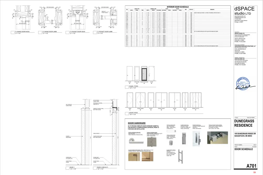
Text of page 59
PAINT INT POCKET BLACK
1/4"
1 1/2"
T1 POCKET DOOR HEAD 3" = 1'-0"
3/4" 1/4"
1/4"
1 1/2"
T1 POCKET DOOR JAMB 3" = 1'-0"
TRIM
WIDTH
101A 101B 103A 103B 104A 104B 104C 105 106A 106B 106C 107A 108 111 112 113
D1 D1 D1 D5 D1 D3 D1 D1 D1 D3 D1 D1 D1 D1 D1 D1
P1 P1 P1 P1 P1 P1 P4 P1 P1 P1 P4 P4 P3 P1 P1 P1
T1 T1 T1 T1 T1 T1 T1 T1 T1 T3 T1 T1 T1
2' - 10" 2' - 10" 2' - 10" 5' - 0" 2' - 8" 2' - 8" 2' - 6" 2' - 10" 2' - 8" 2' - 8" 2' - 6" 3' - 0" 2' - 0 1/2" 2' - 10" 3' - 0" 2' - 10"
8' - 0" 8' - 0" 8' - 0" 8' - 0" 8' - 0" 8' - 0" 8' - 0" 8' - 0" 8' - 0" 8' - 0" 8' - 0" 9' - 6" 7' - 0" 8' - 0" 7' - 11" 8' - 0"
0' - 1 1/2" 0' - 1 1/2" 0' - 1 1/2" 0' - 1 1/2" 0' - 1 1/2" 0' - 1 3/4" 0' - 0 1/2" 0' - 1 1/2" 0' - 1 1/2" 0' - 1 3/4" 0' - 0 1/2" 0' - 0 1/2" 0' - 1 1/2" 0' - 1 1/2" 0' - 1 3/4" 0' - 1 1/2"
200 201A 201B 201C 201D 202 203 205 213
D1 D3 D3 D1 D1 D3 D1 D1 D1
P1 P1 P1 P4 P4 P1 P1 P1 P1
T1 T1 T1 T1 T1 T1 T1
2' - 8" 2' - 10" 2' - 10" 3' - 0" 3' - 0" 2' - 10" 3' - 0" 2' - 8" 3' - 0"
8' - 0" 9' - 6" 9' - 6" 9' - 6" 9' - 6" 9' - 6" 8' - 0" 8' - 0" 9' - 5"
0' - 1 1/2" 0' - 1 3/4" 0' - 1 3/4" 0' - 0 1/2" 0' - 0 1/2" 0' - 1 3/4" 0' - 1 1/2" 0' - 1 1/2" 0' - 1 3/4"
NOMINAL SIZE HEIGHT THICKNESS
DOOR MATERIAL FINISH
FRAME MATERIAL FINISH
MFR
CONTACT
WOOD WOOD WOOD WOOD WOOD WOOD WOOD WOOD WOOD WOOD WOOD WOOD GL-# WOOD WOOD WOOD
TBD TBD TBD TBD TBD TBD TBD TBD TBD TBD TBD TBD TBD TBD TBD TBD
TBD TBD TBD TBD TBD TBD TBD TBD TBD TBD TBD TBD TBD TBD TBD TBD
WOOD WOOD WOOD WOOD WOOD WOOD WOOD WOOD WOOD
TBD TBD TBD TBD TBD TBD TBD TBD TBD
TBD TBD TBD TBD TBD TBD TBD TBD TBD
REMARKS
DOOR TO BE SOLID WOOD, 1-3/8" MIN. THICKNESS, PER IRC R302.5.1
dSPACE studio LTD www.dspacestudio.com info@dspacestudio.com 773.423.2920 2920 North Lincoln Avenue Chicago, IL 60657
GC TO COORD INTERLOCK WITH ELEVATOR MANUFACTURER
ARCHITECT
dSPACE STUDIO LTD KEVIN TOUKOUMIDIS, BOB MCFADDEN, JOSEPH KAFTAN, LILLIAN JONES, & HAYLEY BURROUGHS
2920 N LINCOLN AVE CHICAGO, IL 60657 PHONE: 773.423.2920 STRUCTURAL ENGINEER
GC TO COORD INTERLOCK WITH ELEVATOR MANUFACTURER
GOODFRIEND MAGRUDER STRUCTURE, LLC BOB MAGRUDER & ERIC WHITE
53 W. JACKSON BLVD. SUITE 340 CHICAGO, IL 60604 PHONE: 312.607.9898 GENERAL CONTRACTOR
ZAHN BUILDERS, INC TONY ZAHN & MATT BRUURSEMA
443 DOUGLAS AVE #40 HOLLAND, MI 49424 PHONE: 616.738.9246
FLUSH P1
STILE & RAIL GLASS STILE & RAIL P2 P3
GLASS P4
PANEL TYPES 1/4" = 1'-0"
5/8" GYP BD W/ SCHED FINISH FRY REGLET Z-REVEAL DRMZ 625-375
5/8" GYP BD W/ SCHED FINISH
1/2"
5/8" TYP
PAINTED TO MATCH WALL, REF FINISH SCHED
3/8"
T1 SWING DOOR JAMB 3" = 1'-0"
1 1/2"
DOOR TYPE PANEL
5/8" TYP
SWING D1
DOUBLE SWING D2
POCKET D3
DOUBLE POCKET D4
BI-PASS D5
BI-FOLD D6
DOUBLE BI-FOLD D7
DOOR TYPES 1/4" = 1'-0" 07.08.25
DOOR HARDWARE GC TO PROVIDE COMPLETE DOOR HARDWARE SUBMITTAL FOR ARCHITECT & OWNER REVIEW & APPROVAL PRIOR TO PURCHASE AND INSTALLATION TYPICAL INTERIOR LEVER SET: FSB 1076 LEVER FINISH: BRUSHED STAINLESS STEEL
SHIM AS REQ'D PAINTED WOOD BASE
PAINTED WOOD BASE, REF FINISH SCHED
TYPICAL INTERIOR HINGE: EMTEK SQUARE CORNER HEAVY DUTY HINGE. SOLID BRASS 3.5"x3.5" FINISH: SATIN NICKEL
7 1/2"
1/4"
3/4"
3/4"
REF DOOR SCHED
DOOR
TAG
REF SCHED
1 1/2"
INTERIOR DOOR SCHEDULE
1/4" 1 1/2" 3/4"
3/4"
REF DOOR SCHED
ALIGN
T1 SWING DOOR HEAD 3" = 1'-0"
1/4"
1/4"
REF SCHED
7 1/2"
1 1/2"
3/4"
1 1/2" REF SCHED
1 3/4"
REF SCHED
REF DOOR SCHED
3/4"
1/4"
1/2"
3/4"
1 3/4"
1 1/2"
1/4" 1 1/2" 3/4"
REF DOOR SCHED
1/4"
1/2"
1/4"
1 1/2"
3/4"
1 1/2"
3/4"
1/4"
3/4"
1 1/2"
TYPICAL DOOR STOP: WALL: ROCKWOOD RM871 - US32D (SATIN STAINLESS STL)
TYPICAL DOOR STOP: FLOOR: ROCKWOOD RM850 - US32D (SATIN STAINLESS STL)
CLOSET DOOR PULL: ACCURATE CS2002 FLUSH PULL DUMMY SET FINISH: SATIN NICKEL
POCKET DOOR PULL: ACCURATE POCKET DOOR SET 2002CPDL-4 FINISH: SATIN NICKEL
TYPICAL POCKET DOOR SYSTEM: HAFELE SLIDO CLASSIC FRAME KIT W/ CLASSIC P-40 TRACK SOFT CLOSE / SOFT OPEN
ISSUE FOR PERMIT
DUNEGRASS RESIDENCE 195 DUNEGRASS RIDGE DR SAUGATUCK, MI 49453
0244.01
PROJECT NUMBER: SCALE: GLASS SHOWER DOOR HINGE: METAL CREATIONS INC (1"x1"x4" CHANNEL PROFILE) FINISH: BRUSHED STAINLESS STEEL
SCRIBE BASE TO FLOOR (TYP)
SCRIBE BASE TO FLOOR (TYP)
SCHED FINISH FLOOR
SCHED FINISH FLOOR
BASE-1 12" = 1'-0"
BASE-2 (BID-ALT) 12" = 1'-0"
GLASS DOOR HANDLE: PORTALS COUNTERPOINT 3/4" DIA, 16" DOUBLE SIDED PULL W/ FLAT ENDS FINISH: TBD
AS NOTED
DOOR SCHEDULE
A701 59
Page 60
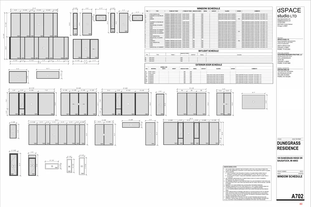
Text of page 60
21' - 9" 4' - 6"
4' - 4 1/2"
2' - 0 1/2"
2' - 0"
4' - 4 1/2"
4' - 4 1/2"
4' - 4"
4' - 11"
WINDOW SCHEDULE
2' - 0 1/2"
2' - 1 1/2"
4' - 2"
TAG
TYPE
FRAME EXT FINISH
FIXED WINDOW WALL CASEMENT W/ FIXED BELOW FIXED AWNING
THERMALLY BROKEN ALUM / BLACK THERMALLY BROKEN ALUM / BLACK THERMALLY BROKEN ALUM / BLACK THERMALLY BROKEN ALUM / BLACK THERMALLY BROKEN ALUM / BLACK THERMALLY BROKEN ALUM / BLACK THERMALLY BROKEN ALUM / BLACK THERMALLY BROKEN ALUM / BLACK THERMALLY BROKEN ALUM / BLACK THERMALLY BROKEN ALUM / BLACK THERMALLY BROKEN ALUM / BLACK THERMALLY BROKEN ALUM / BLACK THERMALLY BROKEN ALUM / BLACK THERMALLY BROKEN ALUM / BLACK THERMALLY BROKEN ALUM / BLACK THERMALLY BROKEN ALUM / BLACK
FRAME INT FINISH
MANUFACTURER
ALUM / BLACK ALUM / BLACK ALUM / BLACK ALUM / BLACK
TBD TBD TBD TBD TBD TBD TBD TBD TBD TBD TBD TBD TBD TBD TBD TBD
MODEL
CONTACT
GLAZING
SCREEN
dSPACE
COMMENTS
2' - 9 1/2"
B2
9' - 2"
B1
9' - 2"
10' - 5"
10' - 5"
11' - 1 1/2"
2' - 9 1/2"
4' - 11"
D1
21' - 6 1/2"
TEMP
10' - 5"
TEMP
TEMP
TEMP
TEMP
TEMP TEMP
D2
TEMP
TEMP
A B1 B2 C D1 D2 E F G H J K L M N O P Q S T U V
TEMP
CASEMENT W/ FIXED BELOW AWNING WINDOW WALL W/ SLIDERS FIXED FIXED WINDOW WALL W/ CASEMENT WINDOW WALL W/ SLIDERS WINDOW WALL W/ CASEMENT FIXED FIXED WINDOW WALL WINDOW WALL W/ SLIDERS FIXED CASEMENT FIXED WINDOW WALL FIXED FIXED WINDOW WALL W/ CASEMENT
THERMALLY BROKEN ALUM / BLACK THERMALLY BROKEN ALUM / BLACK THERMALLY BROKEN ALUM / BLACK THERMALLY BROKEN ALUM / BLACK THERMALLY BROKEN ALUM / BLACK
ALUM / BLACK ALUM / BLACK ALUM / BLACK ALUM / BLACK ALUM / BLACK ALUM / BLACK ALUM / BLACK ALUM / BLACK ALUM / BLACK ALUM / BLACK ALUM / BLACK ALUM / BLACK ALUM / BLACK ALUM / BLACK ALUM / BLACK ALUM / BLACK ALUM / BLACK
TBD TBD TBD TBD TBD TBD TBD TBD TBD TBD TBD TBD TBD TBD TBD TBD
TBD TBD TBD TBD TBD
INSULATED GLASS LOW-E W/ ARGON INSULATED GLASS LOW-E W/ ARGON INSULATED GLASS LOW-E W/ ARGON INSULATED GLASS LOW-E W/ ARGON
YES
INSULATED GLASS LOW-E W/ ARGON INSULATED GLASS LOW-E W/ ARGON INSULATED GLASS LOW-E W/ ARGON INSULATED GLASS LOW-E W/ ARGON INSULATED GLASS LOW-E W/ ARGON INSULATED GLASS LOW-E W/ ARGON INSULATED GLASS LOW-E W/ ARGON INSULATED GLASS LOW-E W/ ARGON INSULATED GLASS LOW-E W/ ARGON INSULATED GLASS LOW-E W/ ARGON INSULATED GLASS LOW-E W/ ARGON INSULATED GLASS LOW-E W/ ARGON INSULATED GLASS LOW-E W/ ARGON INSULATED GLASS LOW-E W/ ARGON INSULATED GLASS LOW-E W/ ARGON INSULATED GLASS LOW-E W/ ARGON INSULATED GLASS LOW-E W/ ARGON
TBD TBD TBD TBD TBD
YES
YES
NFRC CERTIFIED VALUES: U-FACTOR = 0.28, SHGC = 0.2 NFRC CERTIFIED VALUES: U-FACTOR = 0.28, SHGC = 0.2 NFRC CERTIFIED VALUES: U-FACTOR = 0.28, SHGC = 0.2 NFRC CERTIFIED VALUES: U-FACTOR = 0.28, SHGC = 0.2 NFRC CERTIFIED VALUES: U-FACTOR = 0.28, SHGC = 0.2 NFRC CERTIFIED VALUES: U-FACTOR = 0.28, SHGC = 0.2 NFRC CERTIFIED VALUES: U-FACTOR = 0.28, SHGC = 0.2 NFRC CERTIFIED VALUES: U-FACTOR = 0.28, SHGC = 0.2 NFRC CERTIFIED VALUES: U-FACTOR = 0.28, SHGC = 0.2 NFRC CERTIFIED VALUES: U-FACTOR = 0.28, SHGC = 0.2 NFRC CERTIFIED VALUES: U-FACTOR = 0.28, SHGC = 0.2 NFRC CERTIFIED VALUES: U-FACTOR = 0.28, SHGC = 0.2 NFRC CERTIFIED VALUES: U-FACTOR = 0.28, SHGC = 0.2 NFRC CERTIFIED VALUES: U-FACTOR = 0.28, SHGC = 0.2 NFRC CERTIFIED VALUES: U-FACTOR = 0.28, SHGC = 0.2 NFRC CERTIFIED VALUES: U-FACTOR = 0.28, SHGC = 0.2 NFRC CERTIFIED VALUES: U-FACTOR = 0.28, SHGC = 0.2 NFRC CERTIFIED VALUES: U-FACTOR = 0.28, SHGC = 0.2 NFRC CERTIFIED VALUES: U-FACTOR = 0.28, SHGC = 0.2 NFRC CERTIFIED VALUES: U-FACTOR = 0.28, SHGC = 0.2 NFRC CERTIFIED VALUES: U-FACTOR = 0.28, SHGC = 0.2
SKYLIGHT SCHEDULE TAG-
TYPE
FINISH 1
MANUFACTURER -
studio LTD www.dspacestudio.com info@dspacestudio.com 773.423.2920 2920 North Lincoln Avenue Chicago, IL 60657
ARCHITECT
dSPACE STUDIO LTD KEVIN TOUKOUMIDIS, BOB MCFADDEN, JOSEPH KAFTAN, LILLIAN JONES, & HAYLEY BURROUGHS
2920 N LINCOLN AVE CHICAGO, IL 60657 PHONE: 773.423.2920 STRUCTURAL ENGINEER
CONTACT
Glazing
GOODFRIEND MAGRUDER STRUCTURE, LLC
Comments
BOB MAGRUDER & ERIC WHITE TEMP
4' - 8 1/2"
TEMP
TEMP
2' - 0"
6' - 4 1/2"
TEMP
TEMP
4' - 9"
TEMP
TEMP
2' - 0"
TEMP
TEMP
5' - 1"
2' - 1"
TEMP
3' - 11 1/2"
3' - 11"
27' - 0"
TEMP
AA BB CC
3' - 11"
SKYLIGHT SKYLIGHT SKYLIGHT
53 W. JACKSON BLVD. SUITE 340 CHICAGO, IL 60604 PHONE: 312.607.9898
TBD TBD TBD
11' - 10"
EXTERIOR DOOR SCHEDULE 10' - 7"
8' - 2"
TAG
NOMINAL SIZE WIDTH
MATERIAL
HEIGHT
MANUFACTURER
MODEL
CONTACT
GLAZING
SCREEN
GENERAL CONTRACTOR
COMMENTS
ZAHN BUILDERS, INC 3' - 5"
5' - 6"
100 101C 102 107B 204 208A 208B 210
16' - 6 3/4"
20' - 11 1/2" 4' - 6"
2' - 9"
6' - 2 3/4"
4' - 1 3/4"
7' - 6"
4' - 1 3/4"
ALUM / CLAD-2 ALUM / CLAD-2 ALUMINUM ALUMINUM ALUMINUM ALUMINUM ALUMINUM ALUMINUM
TBD TBD TBD TBD TBD TBD TBD TBD
TBD TBD TBD TBD TBD TBD TBD TBD
21' - 6 3/4" 4' - 1 3/4"
4' - 1 3/4"
6' - 3"
2' - 9"
TONY ZAHN & MATT BRUURSEMA
INSULATED GLASS LOW-E W/ ARGON INSULATED GLASS LOW-E W/ ARGON INSULATED GLASS LOW-E W/ ARGON INSULATED GLASS LOW-E W/ ARGON INSULATED GLASS LOW-E W/ ARGON INSULATED GLASS LOW-E W/ ARGON
13' - 4 1/2"
6' - 4 1/2"
6' - 2 1/4"
EQ
3' - 9"
443 DOUGLAS AVE #40 HOLLAND, MI 49424 PHONE: 616.738.9246
NFRC CERTIFIED VALUES: U-FACTOR = 0.28, SHGC = 0.2 NFRC CERTIFIED VALUES: U-FACTOR = 0.28, SHGC = 0.2 NFRC CERTIFIED VALUES: U-FACTOR = 0.28, SHGC = 0.2 NFRC CERTIFIED VALUES: U-FACTOR = 0.28, SHGC = 0.2 NFRC CERTIFIED VALUES: U-FACTOR = 0.28, SHGC = 0.2 NFRC CERTIFIED VALUES: U-FACTOR = 0.28, SHGC = 0.2
6' - 8"
EQ
EQ
3' - 4"
3' - 4"
10' - 6"
10' - 6"
10' - 0"
10' - 6"
6' - 6"
7' - 6"
3' - 0"
TEMP
TEMP
TEMP
TEMP
TEMP
TEMP
TEMP
TEMP
TEMP
26' - 2" 3' - 2 3/8"
3' - 11 1/8"
3' - 11"
2' - 0"
3' - 11"
3' - 11"
2' - 0"
4' - 3"
2' - 6 7/8"
TEMP
4' - 6"
TEMP
6' - 8 3/8"
2' - 6"
TEMP
25' - 9" 4' - 11"
2' - 6"
TEMP
TEMP
4' - 6 5/8"
TEMP
4' - 7 1/8"
4' - 2 7/8"
10' - 6"
10' - 8"
9' - 9"
9' - 6"
6' - 6"
7' - 6"
TEMP
TEMP
8' - 0 5/8"
8' - 5 7/8"
3' - 11"
TEMP
2' - 6"
3' - 0"
10' - 7"
10' - 6"
7' - 6"
10' - 7"
3' - 0"
07.08.25
TEMP
TEMP
TEMP
TEMP
TEMP
TEMP
TEMP
TEMP
TEMP
TEMP
TEMP
TEMP
TEMP
TEMP
TEMP
TEMP
ISSUE FOR PERMIT
DUNEGRASS RESIDENCE
TEMP
3' - 11 3/4" 3' - 6" 2' - 5 1/2" 2' - 1 1/2"
195 DUNEGRASS RIDGE DR SAUGATUCK, MI 49453
BB
CC
TEMP TEMP
TEMP
TEMP
7' - 11 1/2"
TEMP
6' - 1 1/2"
AA
2' - 5 1/2"
9' - 8"
10' - 5"
6' - 1 1/2"
WINDOW GENERAL NOTES
1. ANY GLAZED PANEL GREATER THAN 18" IN WIDTH, WITH A SILL LESS THAN 24" ABOVE THE FLOOR, AND IMMEDIATELY ADJACENT TO ANY DOOR SHALL BE GLAZED WITH SAFETY GLAZING. 2. SAFETY GLAZING: A. SAFETY GLAZING TO BE PROVIDED AT DOORS, AT GLAZED PANELS WIDER THAN 18" ADJACENT TO DOORS, AND AT ANY WINDOW BELOW 2'-0" AFF. CBC 33 (13-124-350) B. ALL SKYLIGHTS TO HAVE 1" INSULATED TEMPERED, LAMINATED SAFETY GLASS. CBC 33 (13-124-370) 3. ANY OPERABLE WINDOW BELOW 2'-0" ABOVE FINISH FLOOR IS TO HAVE A GUARDRAIL INSTALLED 42" AFF. CBC 33 (13-124-320) 4. ALL OPERABLE WINDOWS TO HAVE RESTRICTIONS TO ALLOW THE WINDOW TO BE FIXED IN AN OPEN POSITION OF NOT LESS THAN FOUR INCHES AND NOT MORE THAN SIX INCHES. CONFIRM W/ OWNER. 5. MINIMUM 5.7 SF CLEAR OPENING SHALL BE REQUIRED FOR EGRESS WINDOWS 6. OPERABLE WINDOWS WITH A SILL LESS THAN 36" A.F.F. OR 72" ABOVE FINISHED GRADE OR OTHER SURFACE SHALL NOT ALLOW THE PASSAGE OF A 4" DIAMETER SPHERE. 7. G.C. TO CONFIRM WINDOW SIZES BASED UPON FIELD CONDITIONS AND EXISTING WINDOW SIZES. 8. EVERY WINDOW WHICH IS OPERABLE AND WHICH IS LOCATIED WITHIN 20 FEET OF GROUND LEVEL OR WITHIN 10 FEET OF EXTERIOR STAIR SHALL BE EQUIPPED WITH A LOCK WHICH, WHEN IN THE LOCKED POSITION, WILL PREVENT THE WINDOW FROM BEING OPENED FROM OUTSIDE THE BUILDING. CBC 4 (13-164-050) 9. WINDOW CONTRACTOR TO PROVIDE FULL SET OF SHOP DRAWINGS AND DETAILS FOR APPROVAL. DETAILS SHALL INCLUDE ALL REQUIRED MULL REINFORCEMENT INFORMATION. 10. ALL U-FACTORS TO BE DETERMINED IN ACCORDANCE WITH NFRC TEST PROCEDURE.
PROJECT NUMBER: SCALE:
0244.01 AS NOTED
WINDOW SCHEDULE
A702 60
Page 61
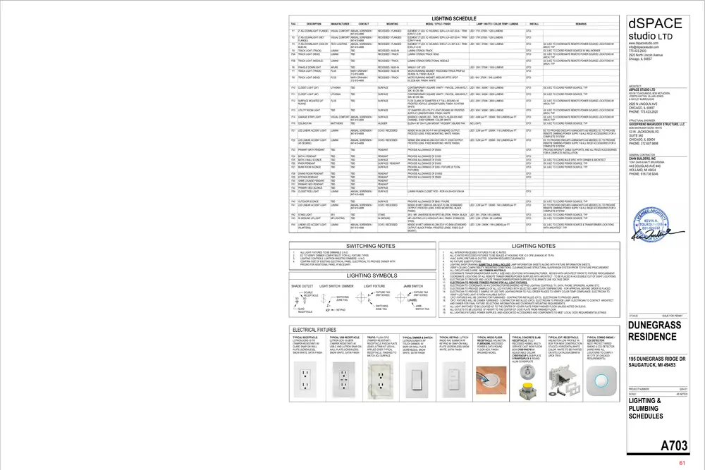
Text of page 61
LIGHTING SCHEDULE TAG
DESCRIPTION
MANUFACTURER
CONTACT
F4 F5A
2" ADJ DOWNLIGHT (FLANGE) VISUAL COMFORT ABIGAIL SORENSEN / 847-410-4699 2" ADJ DOWNLIGHT (WET VISUAL COMFORT ABIGAIL SORENSEN / FLANGE)) 847-410-4699 3" ADJ DOWNLIGHT (HIGH BY TECH LIGHTING ABIGAIL SORENSEN / MUD-IN) 847-410-4699 TRACK LIGHT (TRACK) LUMINII TBD TRACK LIGHT (HEAD) LUMINII TBD
F5B
TRACK LIGHT (MODULE)
LUMINII
F6 F7
PINHOLE DOWNLIGHT TRACK LIGHT (TRACK)
APURE FLOS
F8
TRACK LIGHT (HEAD)
FLOS
F10
CLOSET LIGHT (24")
F11 F12
MODEL / STYLE / FINISH
MOUNTING
INSTALL
CFCI
RECESSED / MUD-IN RECESSED / TRACK
ELEMENT 2" LED, IC HOUSING: E2R-L-LH--927-20-A-I TRIM: LED / 17W /2700K / 1250 LUMENS E2R-F-F-O-W ELEMENT 2" LED, IC HOUSING: E2R-L-LH--927-20-A-I TRIM: LED / 17W /2700K / 1250 LUMENS E2R-F-F-H-W ELEMENT 3" LED, IC HOUSING: E3R-LF-LH--927-2-A-I TRIM: LED / 16W / 2700K / 1440 LUMENS E3R-L-F-O-W LUMINII STENOS TRACK LUMINII STENOS TRACK HEAD
TBD
RECESSED / TRACK
LUMINII STENOS DIRECTIONAL MODULE
CFCI
TBD MARY GRAHAM / 312-810-4699 MARY GRAHAM / 312-810-4699
RECESSED / MUD-IN RECESSED / MUD-IN
MINUS-1 3/8" LED MICRO RUNNING MAGNET, RECESSED TRACK PROFILE 06.6004.14, FINISH: BLACK MICRO RUNNING MAGNET, MEDUIM OPTIC SPOT 03.2236.40A, FINISH: WHITE
LITHONIA
TBD
SURFACE
CLOSET LIGHT (48")
LITHONIA
TBD
SURFACE
SURFACE MOUNTED 24" ROUND
FLOS
TBD
SURFACE
F13
UTILITY ROOM LIGHT
TBD
TBD
SURFACE
F14
GARAGE STRIP LIGHT
SURFACE
F15
CEILING FAN
VISUAL COMFORT ABIGAIL SORENSEN / 847-410-4699 MATTHEWS TBD
F1 F2 F3
RECESSED / FLANGED
LAMP / WATTS / COLOR TEMP / LUMENS
RECESSED / FLANGED RECESSED / FLANGED
RECESSED / TRACK
HUGGER
dSPACE
REMARKS
studio LTD
CFCI CFCI CFCI CFCI
LED / 12W / 2700K / 1000 LUMENS
CFCI CFCI
LED / 6W / 2700K / 545 LUMENS
CFCI
CONTEMPORARY SQUARE VANITY - FMVCSL, 24IN MVOLT, LED / 18W / 3000K / 1300 LUMENS 30K, 90 CRI, BN CONTEMPORARY SQUARE VANITY - FMVCSL, 48IN MVOLT, LED / 34W / 3000K / 2500 LUMENS 30K, 90 CRI, BN FLOS CLARA 24" DIAMETER X 2" TALL (ROUND) W/ LED / 22W / 2700K / 2000 LUMENS FROSTED ACRYLIC LENS/DIFFUSER, FINISH: FU157009 WHITE 12" DIAMTER LED UTILITY LIGHT (ROUND) W/ FROSTED LED / 30W / 3000K / 2800 LUMENS ACRYLIC LENS/DIFFUSER, FINISH: WHITE ESSENCE LINEAR LED - TAPE: ESLTU-16-500-935 AND LED / 4.6W per FT / 3500K / 500 LUMENS per FT CHANNEL: ESSF12296WW. COLOR: WHITE ELIZA-H 56" DIA FLUSH MOUNT "HUGGER" 3-BLADE FAN (NO LIGHT)
GC & EC TO COORDINATE REMOTE POWER SOURCE LOCATIONS W/ ARCH, TYP GC & EC TO COORD POWER SOURCE W/ MILLWORKER GC & EC TO COORDINATE REMOTE POWER SOURCE LOCATIONS W/ ARCH, TYP GC & EC TO COORDINATE REMOTE POWER SOURCE LOCATIONS W/ ARCH, TYP
CFCI
GC & EC TO COORD POWER SOURCE, TYP
CFCI
GC & EC TO COORD POWER SOURCE, TYP
CFCI
GC & EC TO COORDINATE REMOTE POWER SOURCE LOCATIONS W/ ARCH, TYP
CFCI CFCI CFCI
GC & EC TO COORDINATE REMOTE POWER SOURCE LOCATIONS W/ ARCH, TYP GC & EC TO COORDINATE REMOTE POWER SOURCE LOCATIONS W/ ARCH, TYP GC & EC TO COORD POWER SOURCE, TYP
www.dspacestudio.com info@dspacestudio.com 773.423.2920 2920 North Lincoln Avenue Chicago, IL 60657
ARCHITECT
dSPACE STUDIO LTD KEVIN TOUKOUMIDIS, BOB MCFADDEN, JOSEPH KAFTAN, LILLIAN JONES, & HAYLEY BURROUGHS
2920 N LINCOLN AVE CHICAGO, IL 60657 PHONE: 773.423.2920 STRUCTURAL ENGINEER
GOODFRIEND MAGRUDER STRUCTURE, LLC BOB MAGRUDER & ERIC WHITE
F21
LED LINEAR ACCENT LIGHT
LUMINII
ABIGAIL SORENSEN / 847-410-4699
COVE / RECESSED
KENDO M-XX-29K-SO-F-F-WH (STANDARD OUTPUT, FROSTED LENS, FIXED MOUNTING, WHITE FINISH)
LED / 3.2W per FT / 2900K / 118 LUMENS per FT
CFCI
F22
LED LINEAR ACCENT LIGHT (45 DEGREE)
LUMINII
ABIGAIL SORENSEN / 847-410-4699
COVE / RECESSED
KENDO 45M K45M-XX-29K-HO-F-WH-F1 (HIGH OUTPUT, FROSTED LENS, FIXED MOUNTING, WHITE FINISH)
LED / 5.2W per FT / 2900K / 302 LUMENS per FT
CFCI
F23
PRIMARY BATH PENDANT
TBD
TBD
PENDANT
PROVIDE ALLOWANCE OF $5000
CFCI
F24 F25 F26 F27
BATH-2 PENDANT BATH-3 WALL SCONCE PWDR PENDANT BUNK ROOM SCONCE
TBD TBD TBD TBD
TBD TBD TBD TBD
PENDANT SURFACE SURFACE / PENDANT SURFACE
CFCI CFCI CFCI CFCI
F28 F29 F30 F31 F32 F39
DINING ROOM PENDANT KITCHEN PENDANT GAME LOUNGE PENDANT PRIMARY BED PENDANT PRIMARY BED SCONCE CLOSET ROD LIGHT
TBD TBD TBD TBD TBD LUMINII
TBD TBD TBD TBD TBD ABIGAIL SORENSEN / 847-410-4699
PENDANT PENDANT PENDANT PENDANT SURFACE SURFACE
PROVIDE ALLOWANCE OF $1000 PROVIDE ALLOWANCE OF $1000 PROVIDE ALLOWANCE OF $1000 PROVIDE ALLOWANCE OF $300 / FIXTURE (6 TOTAL FIXTURES) PROVIDE ALLOWANCE OF $10000 PROVIDE ALLOWANCE OF $5000
LUMINII RUNDA CLOSET ROD - RCR-XX-29-HO-F-EM-SA
CFCI
F40 F41
OUTDOOR SCONCE LED LINEAR ACCENT LIGHT
TBD LUMINII
TBD ABIGAIL SORENSEN / 847-410-4699
SURFACE COVE / RECESSED
F42 F43
STAKE LIGHT IN GROUND UP-LIGHT
SPJ MP LIGHTING
TBD TBD
STAKE IN GROUND
F44
LINEAR LED ACCENT LIGHT (PLANTERS)
LUMINII
ABIGAIL SORENSEN / 847-410-4699
COVE / RECESSED
PROVIDE ALLOWANCE OF $600 / FIXURE KENDO M WET KMW-XX-30K-SO-F-FC-BK (STANDARD OUTPUT, FROSTED LENS, FIXED MOUNTING, BLACK FINISH) SPJ - MR. UNIVERSE B-3W-SPOT-85-2700K, FINISH: BLACK MP LIGHTING L01-2-W30S-N-F-HB-0, FINISH: STAINLESS STEEL KENDO M WET K45MW-XX-29K-SO-F-FC-BKM (STANDARD OUTPUT, BLACK FINISH, FROSTED LENSE, FIXED CLIP MOUNT).
LED / 3.2W per FT / 3000K / 149 LUMENS per FT
CFCI CFCI
LED / 3W / 2700K / 85 LUMENS LED / 2.5W / 2700K / 80 LUMENS
CFCI CFCI
LED / 3.2W / 2900K / 199 LUMENS per FT
CFCI
FIXTURE TAG
1. 2. 3. 4. 5. 6. 7. 8. 9. 10. 11. 12. 13. 14.
F- (REF SCHED) (JAMB)
15. 16.
LIGHTING SYMBOLS
SO
LIGHT SWITCH / DIMMER
DOUBLE RECEPTACLE SO
QUAD RECEPTACLE
SWITCHING ZONE TAG
Z-KP
KEYPAD
LIGHT FIXTURE FZ-
FIXTURE TAG (REF SCHED)
SWITCHING ZONE TAG
53 W. JACKSON BLVD. SUITE 340 CHICAGO, IL 60604 PHONE: 312.607.9898 GENERAL CONTRACTOR
ZAHN BUILDERS, INC TONY ZAHN & MATT BRUURSEMA
443 DOUGLAS AVE #40 HOLLAND, MI 49424 PHONE: 616.738.9246
GC & EC TO COORD POWER SOURCE, TYP EC TO PROVIDE ENDCAPS & BRACKETS AS NEEDED, EC TO PROVIDE REMOTE DIMMING POWER SUPPLY & ALL REQD ACCESSORIES FOR A COMPLETE SYSTEM GC & EC TO COORD POWER SOURCE, TYP GC & EC TO COORD POWER SOURCE, TYP GC & EC TO COORD POWER SOURCE & TRANSFORMER LOCATIONS WITH ARCHITECT, TYP
LIGHTING NOTES
ALL LIGHT FIXTURES TO BE DIMMABLE U.N.O. EC TO VERIFY DIMMER COMPATIBILITY FOR ALL FIXTURE TYPES LIGHTING CONTROLS: LUNTRON MAESTRO DIMMERS - U.N.O. CONFIRM SIZE OF EXISTING ELECTRICAL PANEL. ELECTRICIAL TO PROVIDE OWNER WITH PRICING FOR ADDITIONAL PANEL IF NECESARY.
SHADE OUTLET
GC & EC TO COORD BULB SPEC WITH OWNER & ARCHITECT GC & EC TO COORD POWER SOURCE, TYP GC & EC TO COORD POWER SOURCE, TYP
CFCI CFCI
SWITCHING NOTES 1. 2. 3. 4.
EC TO PROVIDE ENDCAPS & BRACKETS AS NEEDED, EC TO PROVIDE REMOTE DIMMING POWER SUPPLY & ALL REQD ACCESSORIES FOR A COMPLETE SYSTEM EC TO PROVIDE ENDCAPS & BRACKETS AS NEEDED, EC TO PROVIDE REMOTE DIMMING POWER SUPPLY & ALL REQD ACCESSORIES FOR A COMPLETE SYSTEM PROVIDE AIRCRAFT CABLE SUPPORTS, AND ALL REQ'D ACCESSORIES FOR A COMPLETE INSTALLATION
JAMB SWITCH
JAMB SWITCH TAG
17. 18. 19.
ALL INTERIOR RECESSED FIXTURES TO BE IC RATED. ALL IC RATED RECESSED FIXTURES TO BE SEALED AT HOUSING FOR <2.0 CFM LEAKAGE AT 75 PA. HVAC SUPPLY/RETURN IS DUCTED. CONFIRM REQUIRED CLEARANCES. NO FIXTURE SUBSTITUTIONS. LIGHTING SHOP DRAWING SUBMITTALS SHALL INCLUDE LAMP INFORMATION SHEETS ALONG WITH FIXTURE INFORMATION SHEETS. VERIFY CEILING COMPATIBILITY, MOUNTING CONDITIONS, CLEARANCES AND STRUCTURAL SUSPENSION SYSTEM PRIOR TO FIXTURE PROCUREMENT. ALL CIRCUITS ARE 2-WIRE. NO COMMON NEUTRALS. COORDINATE TRANSFORMER/POWER SUPPLY SIZE AND LOCATIONS WITH MANUFACTURER. REVIEW WITH ARCHITECT PRIOR TO FIXTURE PROCUREMENT. COORDINATE LOCATIONS OF ALL REMOTE TRANSFORMERS/POWER SUPPLIES WITH ARCHITECT - TO BE PLACED IN ACCESSIBLE OUT OF SIGHT LOCATIONS. ELECTRICIAN TO PROVIDE AND LOCATE TRANSFORMERS/POWER SUPPLIES TO ELIMINATE LINE VOLTAGE DROP. ELECTRICIAN TO PROVIDE ITEMIZED PRICING FOR ALL LIGHT FIXTURES. ELECTRICIAN TO COORDINATE W/ A/V CONTRACTOR REGARDING: KEYPAD LIGHTING CONTROLS, TV, DATA, PHONE, SPEAKERS, ALARM, ETC. ELECTRICIAN TO PROVIDE SAMPLES OF ALL LED FIXTURES WITH SELECTED LAMP COLOR TEMPERATURE - FOR APPROVAL BEFORE ORDER IS PLACED. ELECTRICIAN TO PROVIDE 2' SAMPLE OF LED TAPE LIGHTING PRIOR TO FULL ORDER PLACED TO VERIFY COLOR TEMP COMPLIANCE. ELECTRICIAN TO VERIFY LED TAPE LIGHT IS FROM AVAILABLE BATCH. 'CFCI' FIXTURES WILL BE CONTRACTOR FURNISHED - CONTRACTOR INSTALLED (CFCI). ELECTRICIAN TO PROVIDE LAMPS. 'OFCI' FIXTURES WILL BE OWNER FURNISHED - CONTRACTOR INSTALLED (OFCI). ELECTRICIAN TO PROVIDE LAMP, ELECTRICIAN TO CONTACT ARCHITECT AND OWNER FOR FINAL FIXTURE SELECTIONS INFORMATION AND COORDINATE MOUNTING REQUIREMENTS. ALL LIGHT SWITCHES TO BE LOCATED 42" TO THE CENTER OF COVER PLATE FROM FINISHED FLOOR UNLESS NOTED ON ELEVS. ALL OUTLETS TO BE LOCATED 15" HEIGHT TO THE CENTER OF COVE PLATE FROM FINISHED FLOOR. ALL LIGHTING FIXTURES, POWER SUPPLIES, AND ASSOCIATED ACCESSORIES AND COMPONENTS TO MEET LOCAL CODE REQUIREMENTS/LISTINGS. 07.08.25
ELECTRICAL FIXTURES TYPICAL RECEPTACLE: LUTRON SCRS-15-TR (TAMPER-RESISTANT) W/ CLARO SNAP-ON WALL PLATE (SCREWLESS), SNOW WHITE, SATIN FINISH
TYPICAL USB RECEPTACLE: LUTRON SCR-15-UBTR (TAMPER RESISTANT) W/ USB-C AND LUTRON SNAP-ON WALL PLATE (SCREWLESS) SNOW WHITE, SATIN FINISH
TRUFIG: FLUSH GFCI (TAMPER RESISTANT) RECEPTACLE FASCIA PLATE (50401) & TRIM KIT (50314) APPLIED OVER TYPICAL RECEPTACLE; FINISHED TO MATCH ADJ SURFACE
TYPICAL DIMMER & SWITCH: LUTRON SUNNATA RF TOUCH DIMMER, W/ SNAP-ON WALL PLATE (SCREWLESS), SNOW WHITE, SATIN FINISH
TYPICAL KEYPAD: LUTRON RADIO RA3 SUNNATA RF KEYPAD W/ SNAP-ON WALL PLATE (SCREWLESS) SNOW WHITE, SATIN FINISH
TYPICAL WOOD FLOOR RECEPTACLE: ARLINGTON FLBR5420NL RECESSED POWER & DATA ROUND FLOOR BOX, FINISH: BRUSHED NICKEL
TYPICAL CONCRETE SLAB RECEPTACLE: FULLY RECESSED HUBBEL MULTISERVICE CAST IRON FLOOR BOX CFBS1R4CFB W/ ADJUSTABLE COLLAR CFBS1R4CUP & SUB-PLATE S1R4SPDUPLEX & ROUND ALUM COVERPLATE
TYPICAL EXT. RECEPTACLE: ARLINGTON LOW PROFILE 'IN BOX' FOR NEW CONSTRUCTION STUCCO, HORIZONTAL/WHITE COLOR: WHITE (TO BE PAINTED ON SITE) CATALOG# DBHM1W UPC# 77610
TYPICAL COMBO SMOKE / CO2 DETECTOR: NEST PROTECT WIRED SMOKE & CO2 DETECTOR (HARD-WIRE ALL LOCATIONS TO COMPLY W/ CITY OF CHICAGO REQUIREMENTS).
ISSUE FOR PERMIT
DUNEGRASS RESIDENCE 195 DUNEGRASS RIDGE DR SAUGATUCK, MI 49453
0244.01
PROJECT NUMBER: SCALE:
AS NOTED
LIGHTING & PLUMBING SCHEDULES
A703 61
Page 62
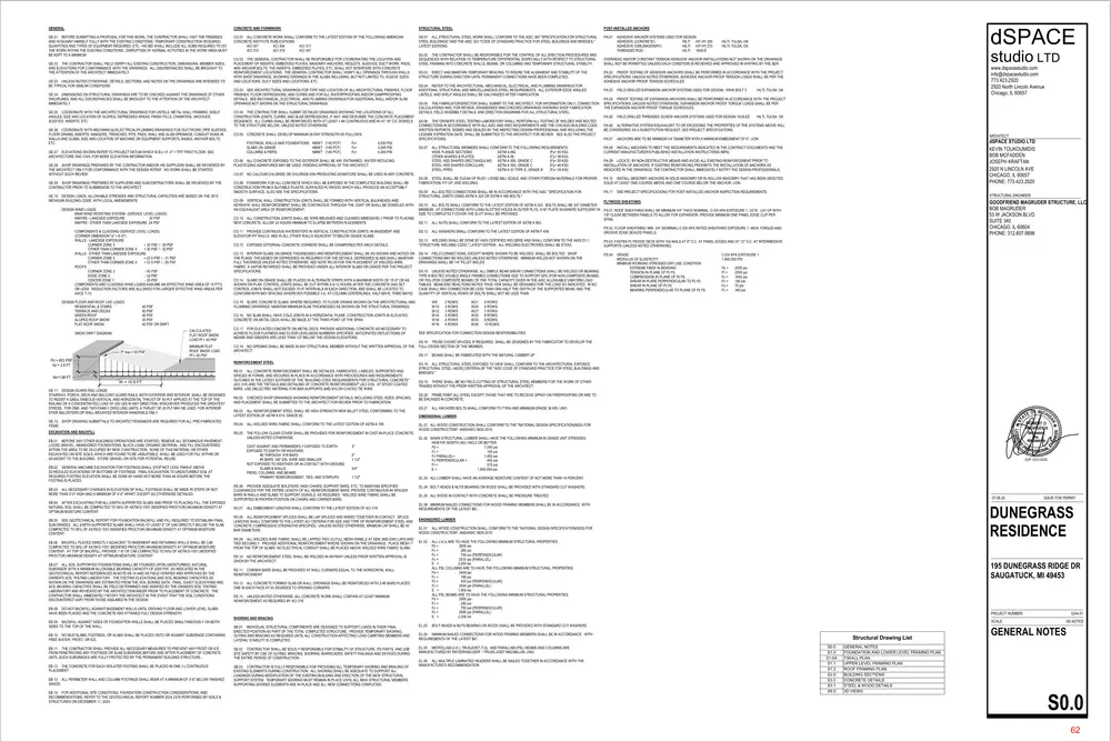
Text of page 62
GENERAL
CONCRETE AND FORMWORK
STRUCTURAL STEEL
POST-INSTALLED ANCHORS
GE.01 BEFORE SUBMITTING A PROPOSAL FOR THIS WORK, THE CONTRACTOR SHALL VISIT THE PREMISES AND ACQUAINT HIMSELF FULLY WITH THE EXISTING CONDITIONS, TEMPORARY CONSTRUCTION REQUIRED, QUANTITIES AND TYPES OF EQUIPMENT REQUIRED, ETC. HIS BID SHALL INCLUDE ALL SUMS REQUIRED TO DO THE WORK WITHIN THE EXISTING CONDITIONS. DISRUPTION OF NORMAL ACTIVITIES IN THE WORK AREA MUST BE KEPT TO A MINIMUM.
CO.01 ALL CONCRETE WORK SHALL CONFORM TO THE LATEST EDITION OF THE FOLLOWING AMERICAN CONCRETE INSTITUTE PUBLICATIONS: ACI 301 ACI 304 ACI 311 ACI 315 ACI 318 ACI 347
SS.01 ALL STRUCTURAL STEEL WORK SHALL CONFORM TO THE AISC 360 "SPECIFICATION FOR STRUCTURAL STEEL BUILDINGS" AND THE AISC 303 "CODE OF STANDARD PRACTICE FOR STEEL BUILDINGS AND BRIDGES," LATEST EDITIONS.
PA.01
GE.02 THE CONTRACTOR SHALL FIELD VERIFY ALL EXISTING CONSTRUCTION, DIMENSIONS, MEMBER SIZES, AND ELEVATIONS FOR CONFORMANCE WITH THE DRAWINGS. ALL DISCREPANCIES SHALL BE BROUGHT TO THE ATTENTION OF THE ARCHITECT IMMEDIATELY. GE.03 UNLESS NOTED OTHERWISE, DETAILS, SECTIONS, AND NOTES ON THE DRAWINGS ARE INTENDED TO BE TYPICAL FOR SIMILAR CONDITIONS. GE.04 DIMENSIONS ON STRUCTURAL DRAWINGS ARE TO BE CHECKED AGAINST THE DRAWINGS OF OTHER DISCIPLINES, AND ALL DISCREPANCIES SHALL BE BROUGHT TO THE ATTENTION OF THE ARCHITECT IMMEDIATELY. GE.05 COORDINATE WITH THE ARCHITECTURAL DRAWINGS FOR LINTELS, METAL WALL FRAMING, SHELF ANGLES, SIZE AND LOCATION OF SLOPES, DEPRESSED AREAS, FINISH FILLS, CHAMFERS, GROOVES, SLEEVES, INSERTS, ETC. GE.06 COORDINATE WITH MECHANICAL/ELECTRICAL/PLUMBING DRAWINGS FOR DUCTWORK, PIPE SLEEVES, FLOOR DRAINS, INSERTS, HANGERS, TRENCHES, PITS, PADS, WALL AND SLAB OPENINGS, CONDUIT RUNS IN WALLS AND SLABS, SIZE AND LOCATION OF MACHINE OR EQUIPMENT SUPPORTS, BASES, ANCHOR BOLTS, ETC
CO.02 THE GENERAL CONTRACTOR SHALL BE RESPONSIBLE FOR COORDINATING THE LOCATION AND PLACEMENT OF INSERTS, EMBEDDED PLATES, MASONRY ANCHORS, REGLETS, SLEEVES, DUCT WORK, PADS, AND ANCHOR BOLTS. THE INSERTS, EMBEDDED PLATES, ETC. SHALL NOT INTERFERE WITH CONCRETE REINFORCEMENT LOCATIONS. THE GENERAL CONTRACTOR SHALL VERIFY ALL OPENINGS THROUGH WALLS WITH SHOP DRAWINGS, SHOWING OPENINGS IN THE SLABS INCLUDING, BUT NOT LIMITED TO, SLEEVE SIZES AND LOCATIONS, DUCT SIZES AND LOCATIONS, ETC. CO.03 SEE ARCHITECTURAL DRAWINGS FOR TYPE AND LOCATION OF ALL ARCHITECTURAL FINISHES, FLOOR FINISHES, FLOOR DEPRESSIONS, AND CURBS AND FOR ALL WATERPROOFING AND/OR DAMPPROOFING DETAILS. SEE MECHANICAL, ELECTRICAL, AND PLUMBING DRAWINGS FOR ADDITIONAL WALL AND/OR SLAB OPENINGS NOT SHOWN ON THE STRUCTURAL DRAWINGS. CO.04 THE CONTRACTOR SHALL SUBMIT DETAILED DRAWINGS SHOWING THE LOCATIONS OF ALL CONSTRUCTION JOINTS, CURBS, AND SLAB DEPRESSIONS, IF ANY, AND DESCRIBE THE CONCRETE PLACEMENT SEQUENCE. ALL CURBS SHALL BE REINFORCED WITH AT LEAST 1-#4 CONTINUOUS AND #3 AT 16" C/C DOWELS TO THE STRUCTURE BELOW, UNLESS NOTED OTHERWISE. CO.05 CONCRETE SHALL DEVELOP MINIMUM 28-DAY STRENGTH AS FOLLOWS: FOOTINGS, WALLS AND FOUNDATIONS NMWT (145 PCF) SLABS ON GRADE NMWT (145 PCF) COLUMNS & PIERS NMWT (145 PCF)
GE.07 ELEVATIONS SHOWN REFER TO PROJECT DATUM WHICH IS EL= 0'- 0" = T/FF FIRST FLOOR. SEE ARCHITECTURE AND CIVIL FOR MORE ELEVATION INFORMATION. GE.08 SHOP DRAWINGS PREPARED BY THE CONTRACTOR AND/OR HIS SUPPLIERS SHALL BE REVIEWED BY THE ARCHITECT ONLY FOR CONFORMANCE WITH THE DESIGN INTENT. NO WORK SHALL BE STARTED WITHOUT SUCH REVIEW. GE.09 SHOP DRAWINGS PREPARED BY SUPPLIERS AND SUBCONTRACTORS SHALL BE REVIEWED BY THE CONTRACTOR PRIOR TO SUBMISSION TO THE ARCHITECT GE.10 DESIGN LOADS, ALLOWABLE STRESSES AND STRUCTURAL CAPACITIES ARE BASED ON THE 2015 MICHIGAN BUILDING CODE, WITH LOCAL AMENDMENTS. DESIGN WIND LOADS MAIN WIND RESISTING SYSTEM (SERVICE LEVEL LOADS) MWFRS - LAKESIDE EXPOSURE 30 PSF MWFRS - OTHER THAN LAKESIDE EXPOSURE 24 PSF
SS.04 REFER TO THE ARCHITECTURAL, MECHANICAL, ELECTRICAL, AND PLUMBING DRAWINGS FOR ADDITIONAL STRUCTURAL AND MISCELLANEOUS STEEL REQUIREMENTS. ALL EXTERIOR EDGE ANGLES, LINTELS, AND SHELF ANGLES SHALL BE GALVANIZED AFTER FABRICATION. SS.05 THE FABRICATOR/ERECTOR SHALL SUBMIT TO THE ARCHITECT, FOR INFORMATION ONLY, CONNECTION CALCULATIONS AND, FOR REVIEW, ENGINEERED AND CHECKED DRAWINGS SHOWING SHOP FABRICATION DETAILS, FIELD ASSEMBLY DETAILS, AND ERECTION DIAGRAMS FOR ALL STRUCTURAL STEEL.
SS.07
CO.06 ALL CONCRETE EXPOSED TO THE EXTERIOR SHALL BE AIRENTRAINED. WATER REDUCING PLASTICIZING ADMIXTURES MAY BE USED, PENDING APPROVAL OF THE ARCHITECT.
MINIMUM FLAT ROOF SNOW LOAD Pf = 40 PSF
Pd = 653 PSF hd = 2.6 FT
W = 10.5 FT GE.11 DESIGN GUARD RAIL LOADS STAIRWAY, PORCH, DECK AND BALCONY GUARD RAILS, BOTH EXTERIOR AND INTERIOR, SHALL BE DESIGNED TO RESIST A SIMULTANEOUS VERTICAL AND HORIZONTAL THRUST OF 50 PLF APPLIED AT THE TOP OF THE RAILING OR A CONCENTRATED LOAD OF 200 LBS IN ANY DIRECTION, WHICHEVER PRODUCES THE GREATEST STRESS. FOR ONEAND TWO-FAMILY DWELLING UNITS, A THRUST OF 20 PLF MAY BE USED FOR INTERIOR STAIR BALUSTERS OR WALL-MOUNTED INTERIOR HANDRAILS ONLY.
CO.08 FORMWORK FOR ALL CONCRETE WHICH WILL BE EXPOSED IN THE COMPLETED BUILDING SHALL BE CONSTRUCTION FROM A SUITABLE PLASTIC SURFACED PLYWOOD WHICH WILL PRODUCE AN ACCEPTABLY SMOOTH SURFACE. ALSO SEE THE SPECIFICATIONS. CO.09 VERTICAL WALL CONSTRUCTION JOINTS SHALL BE FORMED WITH VERTICAL BULKHEADS AND KEYWAYS. WALL REINFORCEMENT SHALL BE CONTINUOUS THROUGH THE JOINT OR SHALL BE DOWELED WITH AN EQUIVALENT AREA OF REINFORCEMENT.
CO.11 PROVIDE CONTINUOUS WATERSTOPS IN VERTICAL CONSTRUCTION JOINTS, IN BASEMENT AND ELEVATOR PIT WALLS, AND IN ALL OTHER WALLS ADJACENT TO BELOW GRADE SLABS. CO.12 EXPOSED EXTERNAL CONCRETE CORNERS SHALL BE CHAMFERED PER ARCH DETAILS. CO.13 INTERIOR SLABS ON GRADE THICKNESSES AND REINFORCEMENT SHALL BE AS SHOWN AND NOTED ON THE PLANS, THICKENED OR DEPRESSED AS REQUIRED FOR THE DETAILS. DEPRESSED SLABS SHALL MAINTAIN FULL THICKNESS UNLESS NOTED OTHERWISE. SEE NOTE RS.09 FOR THE PLACEMENT OF WELDED WIRE FABRIC. A VAPOR RETARDED SHALL BE PROVIDED UNDER ALL INTERIOR SLABS ON GRADE PER THE PROJECT SPECIFICATIONS. CO.14 SLABS ON GRADE SHALL BE PLACED IN ALTERNATE STRIPS WITH A MAXIMUM WIDTH OF 15'-0" OR AS SHOWN ON PLAN. CONTROL JOINTS SHALL BE CUT WITHIN A 8-12 HOURS AFTER THE CONCRETE HAS SET. CONTROL JOINTS SHALL NOT EXCEED 15'-0" INTERVALS IN EACH DIRECTION, AND SHALL BE LOCATED TO CONFORM WITH BAY SPACING WHEREVER POSSIBLE (I.E. AT COLUMN CENTERLINES, HALF-BAYS, THIRD-BAYS)
CO.17 FOR ELEVATED CONCRETE ON METAL DECK, PROVIDE ADDITIONAL CONCRETE AS NECESSARY TO ACHIEVE FLOOR FLATNESS AND FLOOR LEVELNESS NUMBERS SPECIFIED. ANTICIPATED DEFLECTIONS OF MEANS AND GIRDERS ARE LESS THAN 1/2" BELOW THE DESIGN ELEVATIONS. CO.18 NO OPENING SHALL BE MADE IN ANY STRUCTURAL MEMBER WITHOUT THE WRITTEN APPROVAL OF THE ARCHITECT.
RS.01 ALL CONCRETE REINFORCEMENT SHALL BE DETAILED, FABRICATED, LABELED, SUPPORTED AND SPACED IN FORMS, AND SECURED IN PLACE IN ACCORDANCE WITH PROCEDURES AND REQUIREMENTS OUTLINES IN THE LATEST EDITIONS OF THE "BUILDING CODE REQUIREMENTS FOR STRUCTURAL CONCRETE" (ACI 318) AND THE "DETAILS AND DETAILING OF CONCRETE REINFORCEMENT" (ACI 315). AT EPOXY COATED BARS, USE DIELECTRIC MATERIAL FOR BAR SUPPORTS AND NYLON COATED TIE WIRE. RS.02 CHECKED SHOP DRAWINGS SHOWING REINFORCEMENT DETAILS, INCLUDING STEEL SIZES, SPACING, AND PLACEMENT SHALL BE SUBMITTED TO THE ARCHITECT FOR REVIEW PRIOR TO FABRICATION. RS.03 ALL REINFORCEMENT STEEL SHALL BE HIGH STRENGTH NEW BILLET STEEL CONFORMING TO THE LATEST EDITION OF ASTM A 615. GRADE 60. RS.04
ALL WELDED WIRE FABRIC SHALL CONFORM TO THE LATEST EDITION OF ASTM A 185
EXCAVATION AND BACKFILL
RS.05
THE FOLLOW CLEAR COVER SHALL BE PROVIDED FOR REINFORCEMENT IN CAST-IN-PLACE CONCRETE, UNLESS NOTED OTHERWISE:
EB.01 BEFORE ANY OTHER BUILDINGS OPERATIONS ARE STARTED, REMOVE ALL BITUMINOUS PAVEMENT, LOOSE GRAVEL, ABANDONED FOUNDATIONS, BLACK LOAM, ORGANIC MATERIAL, AND FILL ENCOUNTERED WITHIN THE AREA TO BE OCCUPIED BY NEW CONSTRUCTION. NONE OF THIS MATERIAL OR OTHER EXCAVATED ON-SITE SOILS, WHICH ARE FOUND TO BE UNSUITABLE, SHALL BE USED FOR FILL WITHIN OR ADJACENT TO THE BUILDING. STORE GRAVEL ON SITE FOR POTENTIAL REUSE.
CAST AGAINST AND PERMANENTLY EXPOSED TO EARTH EXPOSED TO EARTH OR WEATHER: #6 THROUGH #18 BARS #5 BARS, 5/8" DIA. WIRE AND SMALLER NOT EXPOSED TO WEATHER OR IN CONTACT WITH GROUND: SLABS & WALLS PIERS, COLUMNS, AND BEAMS: PRIMARY REINFORCEMENT, TIES, AND STIRRUPS
EB.02 GENERAL MACHINE EXCAVATION FOR FOOTINGS SHALL STOP NOT LESS THAN 6" ABOVE SCHEDULED ELEVATIONS OF BOTTOMS OF FOOTINGS. FINAL EXCAVATION TO UNDISTURBED SOIL AT REQUIRED FOOTING ELEVATION SHALL BE DONE BY HAND NOT MORE THAN 48 HOURS BEFORE THE FOOTING IS PLACED.
EB.04 AFTER EXCAVATING FOR ALL EARTH-SUPPORTED SLABS AND PRIOR TO PLACING FILL, THE EXPOSED NATURAL SOIL SHALL BE COMPACTED TO 95% OF ASTM D-1557 (MODIFIED PROCTOR) MAXIMUM DENSITY AT OPTIMUM MOISTURE CONTENT. EB.05 SEE GEOTECHNICAL REPORT FOR FOUNDATION BACKFILL AND FILL REQUIRED TO ESTABLISH FINAL SUB-GRADES. ALL EARTH-SUPPORTED SLABS SHALL HAVE AT LEAST 6" OF CA6 DIRECTLY BELOW THE SLAB COMPACTED TO 95% OF ASTM D-1557 (MODIFIED PROCTOR) MAXIMUM DENSITY AT OPTIMUM MOISTURE CONTENT. EB.06 BACKFILL PLACED DIRECTLY ADJACENT TO BASEMENT AND RETAINING WALLS SHALL BE CA6 COMPACTED TO 95% OF ASTM D-1557 (MODIFIED PROCTOR) MAXIMUM DENSITY AT OPTIMUM MOISTURE CONTENT. AT TOP OF BACKFILL, PROVIDE 1'-6" OF CA6 COMPACTED TO 95% OF ASTM D-1557 (MODIFIED PROCTOR) MAXIMUM DENSITY AT OPTIMUM MOISTURE CONTENT. EB.07 ALL SOIL SUPPORTED FOUNDATIONS SHALL BE FOUNDED UPON UNDISTURBED, NATURAL SUBGRADE WITH A MINIMUM ALLOWABLE BEARING CAPACITY OF 2000 PSF, AS INDICATED IN THE GEOTECHNICAL REPORT REFERENCED IN NOTE EB.14 AND AS FIELD VERIFIED AND APPROVED BY THE OWNER'S SOIL TESTING LABORATORY. THE FOOTING ELEVATIONS AND SOIL BEARING CAPACITIES AS SHOWN ON THE DRAWINGS ARE ESTIMATED FROM THE SOIL BORING DATA. FINAL, EXACT ELEVATIONS AND SOIL BEARING CAPACITIES SHALL BE FIELD DETERMINED AND VERIFIED BY THE OWNER'S SOIL TESTING LABORATORY AND REVIEWED BY THE ARCHITECT/ENGINEER PRIOR TO PLACEMENT OF CONCRETE. THE CONTRACTOR SHALL IMMEDIATELY NOTIFY THE ARCHITECT IN THE EVENT THAT THE SOIL CONDITIONS ENCOUNTERED VARY FROM THOSE ASSUMED IN THE DESIGN.
HILTI, TULSA. OK
PA.04 PROOF TESTING OF EXPANSION ANCHORS SHALL BE PERFORMED IN ACCORDANCE WITH THE PROJECT SPECIFICATIONS. UNLESS NOTED OTHERWISE, EXPANSION ANCHOR PROOF TORQUE LOADS SHALL BE PER THE EXPANSION ANCHOR PROOF TORQUE SCHEDULES. FIELD DRILLED THREADED SCREW ANCHOR SYSTEMS USED FOR DESIGN: HUS-EZ
HILTI, TULSA. OK
PA.06 ALTERNATIVE SYSTEM EQUIVALENT TO OR EXCEEDING THE PROPERTIES OF THE SYSTEMS ABOVE WILL BE CONSIDERED AS A SUBSTITUTION REQUEST. SEE PROJECT SPECIFICATIONS. PA.07
ARCHITECT
ANCHORS ARE TO BE MINIMUM 3/4' DIAMETER WITH A MINIMUM EMBEDMENT OF 6", UON.
dSPACE STUDIO LTD KEVIN TOUKOUMIDIS BOB MCFADDEN JOSEPH KRAFTAN 2920 N LINCOLN AVE CHICAGO, IL 60657 PHONE: 773.423.2920
PA.08 INSTALL ANCHORS TO MEET THE REQUIREMENTS INDICATED IN THE CONTRACT DOCUMENTS AND THE CURRENT MANUFACTURER'S PUBLISHED INSTALLATION INSTRUCTIONS (MPII). PA.09 LOCATE, BY NON-DESTRUCTIVE MEANS AND AVOID ALL EXISTING REINFORCEMENT PRIOR TO INSTALLATION OF ANCHORS. IF EXISTING REINFORCING PROHIBITS THE INSTALLATION OF ANCHORS AS INDICATED IN THE DRAWINGS, THE CONTRACTOR SHALL IMMEDIATELY NOTIFY THE DESIGN PROFESSIONALS.
PA.11
PS.03. FASTEN PLYWOOD DECK WITH 10d NAILS AT 6" O.C. AT PANEL EDGES AND AT 12" O.C. AT INTERMEDIATE SUPPORTS (UNLESS NOTED OTHERWISE).
SS.14 FIELD CONNECTIONS, EXCEPT WHERE SHOWN TO BE WELDED, SHALL BE BOLTED. SHOP CONNECTIONS MAY BE WELDED UNLESS NOTED OTHERWISE. MINIMUM WELDS NOT SHOWN ON THE DRAWINGS SHALL BE 1/4" FILLET WELDS.
PS.04. GRADE: MODULUS OF ELASTICITY: MINIMUM WORKING STRESSES DRY USE CONDITION EXTREME FIBER IN BENDING TENSION IN PLANE OF PLYS. COMPRESSION IN PLANE OF PLYS SHEAR IN PLANE PERPENDICULAR TO PLYS. SHEAR IN PLANE OF PLYS. BEARING PERPENDICULAR TO PLANE OF PLYS.
SS.15 UNLESS NOTED OTHERWISE, ALL SIMPLE BEAM SHEAR CONNECTIONS SHALL BE WELDED OR BEARING TYPE N BOLTED DOUBLE ANGLE FRAMED CONNECTIONS SIZE TO SUPPORT 60% (FOR NON-COMPOSITE BEAMS) OR 75% (FOR COMPOSITE BEAMS) OF THE TOTAL CAPACITY GIVEN IN THE AISC ALLOWABLE UNIFORM LOAD TABLES. BEAM END REACTIONS NOTED THUS 100K SHALL BE DESIGNED FOR THE LOAD SO INDICATED. IN NO CASE SHALL ANY CONNECTION BE LESS THAN ONE-HALF THE DEPTH OF THE SUPPORTED BEAM, AND THE QUANTITY OF VERTICAL ROWS OF BOLTS SHALL NOT BE LESS THAN: W8: W10: W12: W14: W16: W18:
W21: W24: W27: W30: W33: W36:
RS.08 ALL REINFORCEMENT SPLICES SHALL BE LAP SPLICED AND WIRED TOGETHER IN CONTACT. SPLICE LENGTHS SHALL CONFORM TO THE LATEST ACI CRITERIA FOR SIZE AND TYPE OF REINFORCEMENT STEEL AND CONCRETE COMPRESSIVE STRENGTHS SPECIFIED. UNLESS NOTED OTHERWISE, MINIMUM LAP SHALL BE 40 BAR DIAMETERS. RS.09 ALL WELDED WIRE FABRIC SHALL BE LAPPED TWO (2) FULL MESH PANELS AT SIDE AND END LAPS AND TIED SECURELY. PROVIDE ADDITIONAL REINFORCEMENT WHERE SHOWN ON THE DRAWINGS. PLACE MESH 1" FROM THE TOP OF SLABS. NO ELECTRICAL CONDUIT SHALL BE PLACED ABOVE WELDED WIRE FABRIC SLABS.
C-DX APA EXPOSURE 1 1,800,000 PSI Fb = Ft = Fc = Fv = Fs = Fc =
2000 psi 2000 psi 1640 psi 190 psi 75 psi 340 psi
SEE SPECIFICATION FOR CONNECTION DESIGN RESPONSIBILITIES SS.16 TRUSS CHORD SPLICES, IF REQUIRED, SHALL BE DESIGNED BY THE FABRICATOR TO DEVELOP THE FULL CROSS SECTION OF THE MEMBER. BEAMS SHALL BE FABRICATED WITH THE NATURAL CAMBER UP.
SS.18 ALL STRUCTURAL STEEL EXPOSED TO VIEW SHALL CONFORM TO THE ARCHITECTURAL EXPOSED STRUCTURAL STEEL (AESS) CRITERIA OF THE "AISC CODE OF STANDARD PRACTICE FOR STEEL BUILDINGS AND BRIDGES." SS.19 THERE SHALL BE NO FIELD CUTTING OF STRUCTURAL STEEL MEMBERS FOR THE WORK OF OTHER TRADES WITHOUT THE PRIOR WRITTEN APPROVAL OF THE ARCHITECT. SS.20 PRIME PAINT ALL STEEL EXCEPT THOSE THAT ARE TO RECEIVE SPRAY-ON FIREPROOFING OR ARE TO BE ENCASED IN CONCRETE. SS.21
ALL ANCHORS BOLTS SHALL CONFORM TO F1554 AND MINIMUM GRADE 36 KSI, UNO.
DIMENSIONAL LUMBER DL.01 ALL WOOD CONSTRUCTION SHALL CONFORM TO THE "NATIONAL DESIGN SPECIFICATION(NDS) FOR WOOD CONSTRUCTION", ANSI/AWC NDS-2015.
DL.03 ALL LUMBER SHALL HAVE AN AVERAGE MOISTURE CONTENT OF NOT MORE THAN 19 PERCENT.
ALL EMBEDMENT LENGTHS SHALL CONFORM TO THE LATEST EDITION OF ACI 318.
GOODFRIEND MAGRUDER STRUCTURE, LLC BOB MAGRUDER 53 W JACKSON BLVD. SUITE 340 CHICAGO, IL 60604 PHONE: 312.607.9898
6 ROWS 6 ROWS 7 ROWS 8 ROWS 9 ROWS 10 ROWS
1 1/2"
RS.06 PROVIDE ADEQUATE BOLSTERS, HIGH CHAIRS, SUPPORT BARS, ETC. TO MAINTAIN SPECIFIED CLEARANCES FOR THE ENTIRE LENGTH OF ALL REINFORCEMENT BARS. PROVIDE CONTINUOUS #4 SPACER BARS IN WALLS AND SLABS TO SUPPORT DOWELS, AS REQUIRED. WELDED WIRE FABRIC SHALL BE SUPPORTED IN PROPER POSITION ON CHAIRS AND CARRIER BARS. RS.07
2 ROWS 2 ROWS 3 ROWS 3 ROWS 4 ROWS 5 ROWS
3/4"
2" 1 1/2"
STRUCTURAL ENGINEER
SS.13 WELDING SHALL BE DONE BY AWS CERTIFIED WELDERS AND SHALL CONFORM TO THE AWS D1.1 "STRUCTURE WELDING CODE," LATEST EDITION. ALL WELDING ELECTRODES SHALL BE E70XX.
DL.02 SAWN STRUCTURAL LUMBER SHALL HAVE THE FOLLOWING MINIMUM IN GRADE UNIT STRESSES: HEM FIR (NORTH) NO.1/NO.2 OR BETTER Fb = 1,000 psi Fv = 145 psi Fc PARALLEL= 1,450 psi Fc PERPENDICULAR = 405 psi Ft = 575 psi E= 1,600,000 psi
SEE PROJECT SPECIFICATIONS FOR POST-INSTALLED ANCHOR INSPECTION REQUIREMENTS.
PLYWOOD SHEATHING SS.10 ALL BOLTS SHALL CONFORM TO THE LATEST EDITION OF ASTM A 325. BOLTS SHALL BE 3/4" DIAMETER MINIMUM. AT CONNECTIONS WITH LONG-SLOTTED HOLES IN OUTER PLYS, 5/16" PLATE WASHERS SUFFICIENT IN PS.01. ROOF SHEATHING SHALL BE MINIMUM 3/4" THICK NOMINAL. C-DX APA EXPOSURE 1, 32/16. LAY UP WITH SIZE TO COMPLETELY COVER THE SLOT SHALL BE PROVIDED. 1/8" CLEAR BETWEEN PANELS TO ALLOW FOR EXPANSION. PROVIDE MINIMUM ONE PANEL EDGE CLIP PER SPAN. SS.11 ALL NUTS SHALL CONFORM TO THE LATEST EDITION OF ASTM A 563. PS.02. FLOOR SHEATHING: MIN. 3/4" (NOMINAL) C-DX APA RATED SHEATHING EXPOSURE 1, 48/24 TONGUE-ANDSS.12 ALL WASHERS SHALL CONFORM TO THE LATEST EDITION OF ASTM F 436. GROOVE EDGE SEALED PANELS.
EXP 10/31/2026
DL.04 BOLT HEADS & NUTS BEARING ON WOOD SHALL BE PROVIDED WITH STANDARD CUT WASHERS. DL.05 ALL WOOD IN CONTACT WITH CONCRETE SHALL BE PRESSURE TREATED.
07.08.25
DL.06 MINIMUM NAILED CONNECTIONS FOR WOOD FRAMING MEMBERS SHALL BE IN ACCORDANCE WITH REQUIREMENTS OF THE LATEST IBC.
EL.01 ALL WOOD CONSTRUCTION SHALL CONFORM TO THE "NATIONAL DESIGN SPECIFICATION(NDS) FOR WOOD CONSTRUCTION", ANSI/AWC NDS-2015. EL.02
RS.10 NO REINFORCEMENT STEEL SHALL BE WELDED IN ANYWAY UNLESS PRIOR WRITTEN APPROVAL IS GIVEN BY THE ARCHITECT. RS.11 CORNER BARS SHALL BE PROVIDED AT WALL CORNERS EQUAL TO THE HORIZONTAL WALL REINFORCEMENT. RS.12 ALL CONCRETE FORMED SLAB OR WALL OPENINGS SHALL BE REINFORCED WITH 2-#5 BARS PLACED ONE IN EACH FACE AT 45 DEGREES TO OPENING CORNERS. RS.13 UNLESS NOTED OTHERWISE, ALL CONCRETE WORK SHALL CONTAIN AT LEAST MINIMUM REINFORCEMENT AS REQUIRED BY ACI 318.
ALL LVL's ARE TO HAVE THE FOLLOWING MINIMUM STRUCTURAL PROPERTIES: Fb = 2600 psi Fv = 285 psi Fc = 750 psi (PERPENDICULAR) Fc = 2510 psi (PARALLEL) E = 2,000 ksi ALL PSL COLUMNS ARE TO HAVE THE FOLLOWING MINIMUM STRUCTURAL PROPERTIES: Fb = 2400 psi Fv = 190 psi Fc = 425 psi (PERPENDICULAR) Fc = 2500 psi (PARALLEL) E = 1,800 ksi ALL PSL BEAMS ARE TO HAVE THE FOLLOWING MINIMUM STRUCTURAL PROPERTIES: Fb = 2900 psi Fv = 290 psi Fc = 750 psi (PERPENDICULAR) Fc = 2900 psi (PARALLEL) E = 2,200 ksi
195 DUNEGRASS RIDGE DR SAUGATUCK, MI 49453
PROJECT NUMBER: SCALE:
EL.03
EB.10 NO MUD SLABS, FOOTINGS, OR SLABS SHALL BE PLACED ONTO OR AGAINST SUBGRADE CONTAINING FREE WATER, FROST, OR ICE. EB.11 THE CONTRACTOR SHALL PROVIDE ALL NECESSARY MEASURES TO PREVENT ANY FROST OR ICE FROM PENETRATING ANY FOOTINGS OR SLAB SUBGRADE BEFORE AND AFTER PLACEMENT OF CONCRETE UNTIL SUCH SUBGRADES ARE FULLY PROTECTED BY THE PERMANENT BUILDING STRUCTURE.
SB.02 CONTRACTOR SHALL BE SOLELY RESPONSIBLE FOR STABILITY OF STRUCTURE, ITS PARTS, AND JOB SITE SAFETY BY USE OF GUYING, BRACING, SHORING, BARRICADES, SAFETY RAILINGS AND DEVICES DURING THE ENTIRE PERIOD OF CONSTRUCTION.
EL.05 MICROLLAM (LVL), TRUSJOIST (TJI), AND PARALLAM (PSL) BEAMS AND COLUMNS ARE MANUFACTURED BY WEYERHAEUSER / TRUSS-JOIST MACMILLAN, UNO.
EB.12 THE CONCRETE FOR EACH ISOLATED FOOTING SHALL BE PLACED IN ONE (1) CONTINUOUS PLACEMENT.
SB.03 CONTRACTOR IS FULLY RESPONSIBLE FOR PROVIDING ALL TEMPORARY SHORING AND BRACING OF EXISTING ELEMENTS DURING CONSTRUCTION. ALL SHORING SHALL BE ADEQUATE TO SUPPORT ALL LOADINGS DURING MODIFICATION OF THE EXISTING BUILDING AND ERECTION OF THE NEW STRUCTURAL SUPPORT SYSTEM. TEMPORARY SHORING MUST REMAIN IN PLACE UNTIL ALL NEW STRUCTURAL MEMBERS SUPPORTING SHORED ELEMENTS ARE IN PLACE AND ALL NEW CONNECTIONS COMPLETED.
BOLT HEADS & NUTS BEARING ON WOOD SHALL BE PROVIDED WITH STANDARD CUT WASHERS.
EL.04 MINIMUM NAILED CONNECTIONS FOR WOOD FRAMING MEMBERS SHALL BE IN ACCORDANCE WITH REQUIREMENTS OF THE LATEST IBC.
EL.06 ALL MULTIPLE LAMINATED HEADERS SHALL BE NAILED TOGETHER IN ACCORDANCE WITH THE MANUFACTURE'S RECOMMENDATION
ISSUE FOR PERMIT
DUNEGRASS RESIDENCE
ENGINEERED LUMBER
SB.01 INDIVIDUAL STRUCTURAL COMPONENTS ARE DESIGNED TO SUPPORT LOADS IN THEIR FINAL ERECTED POSITION AS PART OF THE TOTAL COMPLETED STRUCTURE. PROVIDE TEMPORARY SHORING, GUYING AND BRACING AS REQUIRED UNTIL ALL CONSTRUCTION AFFECTING LOAD CARRYING MEMBERS AND LATERAL STABILITY IS COMPLETED.
EB.14 FOR ADDITIONAL SITE CONDITIONS, FOUNDATION CONSTRUCTION CONSIDERATIONS, AND RECOMMENDATIONS, REFER TO THE GEOTECHNICAL REPORT NUMBER 2024.2378 PERFORMED BY SOILS & STRUCTURES ON DECEMBER 11, 2024.
FIELD DRILLED EXPANSION ANCHOR SYSTEMS USED FOR DESIGN. KWIK BOLT 3
SS.09 ALL BOLTED CONNECTIONS SHALL BE IN ACCORDANCE WITH THE AISC "SPECIFICATION FOR STRUCTURAL JOINTS USING ASTM A 325 OR ASTM A 490 BOLTS."
SHORING AND BRACING
EB.13 ALL PERIMETER WALL AND COLUMN FOOTINGS SHALL BEAR AT A MINIMUM OF 3'-6" BELOW FINISHED GRADE.
PA.03
PA.10 INSTALL MASONRY ANCHORS IN SOLID MASONRY OR IN HOLLOW MASONRY THAT HAS BEEN GROUTED SOLID AT LEAST ONE COURSE ABOVE ANO ONE COURSE BELOW THE ANCHOR, UON.
EB.08 DO NOT BACKFILL AGAINST BASEMENT WALLS UNTIL GROUND FLOOR AND LOWER LEVEL SLABS HAVE BEEN PLACED AND THE CONCRETE HAS ATTAINED FULL DESIGN STRENGTH. EB.09 BACKFILL AGAINST SIDES OF FOUNDATION WALLS SHALL BE PLACED SIMULTANEOUSLY ON BOTH SIDES TO THE TOP OF THE WALL.
www.dspacestudio.com info@dspacestudio.com 773.423.2920 2920 North Lincoln Avenue Chicago, IL 60657
PA.02 PROOF TESTING OF ADHESIVE ANCHORS SHALL BE PERFORMED IN ACCORDANCE WITH THE PROJECT SPECIFICATIONS. UNLESS NOTED OTHERWISE, ADHESIVE ANCHOR PROOF TENSION LOADS SHALL BE PER THE ADHESIVE ANCHOR PROOF TENSION SCHEDULES.
SS.08 STEEL SHALL BE CLEAN OF RUST, LOOSE MILL SCALE, AND OTHER FOREIGN MATERIALS FOR PROPER FABRICATION, FIT-UP, AND WELDING.
SS.17
GE.12 SHOP DRAWING SUBMITTALS TO ARCHITECT/ENGINEER ARE REQUIRED FOR ALL PRE-FABRICATED ITEMS.
EB.03 ALL NECESSARY CHANGES IN ELEVATION OF WALL FOOTINGS SHALL BE MADE IN STEPS OF NOT MORE THAN 2'-0" HIGH AND A MINIMUM OF 4'-0" APART, EXCEPT AS OTHERWISE DETAILED.
studio LTD
CO.07 NO CALCIUM CHLORIDE OR CHLORIDE-ION PRODUCING ADMIXTURE SHALL BE USED IN ANY CONCRETE.
REINFORCEMENT STEEL
hb=1.88 FT
ALL STRUCTURAL MEMBERS SHALL CONFORM TO THE FOLLOWING REQUIREMENTS: WIDE FLANGE SECTIONS ASTM A 992 (Fy= 50 KSI) OTHER SHAPES & PLATES ASTM A 36 (Fy= 36 KSI) STEEL HSS SHAPES (RECTANGULAR) ASTM A 500, GRADE C (Fy= 50 KSI) STEEL HSS SHAPES (CIRCULAR) ASTM A 500, GRADE C (Fy= 46 KSI) STEEL PIPES ASTM A 53 TYPE E, GRADE B (Fy= 35 KSI)
dSPACE
HILTI, TULSA, OK HILTI, TULSA, OK
OVERHEAD AND/OR CONSTANT TENSION ADHESIVE ANCHOR INSTALLATIONS NOT SHOWN ON THE DRAWINGS SHALL NOT BE PERMITTED UNLESS EACH CONDITION IS REVIEWED AND APPROVED IN WRITING BY THE SER.
PA.05 SS.06 THE OWNER'S STEEL TESTING LABORATORY SHALL PERFORM ALL TESTING OF WELDED AND BOLTED CONNECTIONS IN ACCORDANCE WITH ALL AISC AND AWS REQUIREMENTS AND THE CHICAGO BUILDING CODE. WRITTEN REPORTS, SIGNED AND SEALED BY THE INSPECTING DESIGN PROFESSIONAL AND INCLUDING THE LICENSE EXPIRATION DATE, SHALL BE SUBMITTED TO THE ARCHITECT FOR REVIEW. SEE ALSO THE PROJECT SPECIFICATIONS.
CO.16 NO SLAB SHALL HAVE COLD JOINTS IN A HORIZONTAL PLANE. CONSTRUCTION JOINTS IN ELEVATED CONCRETE ON METAL DECK SHALL BE MADE AT THE THIRD POINT OF THE SPAN.
CALCULATED FLAT ROOF SNOW LOAD Pf = 40 PSF P max = 93 PSF
SS.03 ERECT AND MAINTAIN TEMPORARY BRACING TO INSURE THE ALIGNMENT AND STABILITY OF THE STRUCTURE DURING ERECTION UNTIL PERMANENT CONNECTIONS HAVE BEEN COMPLETED.
CO.15 SLOPE CONCRETE SLABS, WHERE REQUIRED, TO FLOOR DRAINS SHOWN ON THE ARCHITECTURAL AND PLUMBING DRAWINGS. MAINTAIN MINIMUM SLAB THICKNESSES AS SHOWN ON THE STRUCTURAL DRAWINGS.
40 PSF 60 PSF 40 PSF 35 PSF 40 PSF OR DRIFT
SNOW DRIFT DIAGRAM:
4,000 PSI 3,500 PSI 4,000 PSI
CO.10 ALL CONSTRUCTION JOINTS SHALL BE WIRE-BRUSHED AND CLEANED IMMEDIATELY PRIOR TO PLACING NEW CONCRETE. ALLOW 24 HOURS MINIMUM TO ELAPSE BETWEEN PLACEMENTS.
COMPONENTS & CLADDING (SERVICE LEVEL LOADS) (CORNER DIMENSION "a" = 6'-0") WALLS - LAKESIDE EXPOSURE CORNER ZONE 5 + 30 PSF / - 39 PSF OTHER THAN CORNER ZONE 4 + 30 PSF / - 32 PSF WALLS - OTHER THAN LAKESIDE EXPOSURE CORNER ZONE 5 + 23.5 PSF / - 31 PSF OTHER THAN CORNER ZONE 4 + 23.5 PSF / - 25 PSF ROOFS CORNER ZONE 3 - 50 PSF EDGE ZONE 2 - 33 PSF CENTER ZONE 1 - 20 PSF COMPONENTS AND CLADDING WIND LOADS ASSUME AN EFFECTIVE WIND AREA OF 10 FT^2 OR LESS. REDUCTION FACTORS ARE ALLOWED FOR LARGER EFFECTIVE WIND AREAS PER ASCE 7-10. DESIGN FLOOR AND ROOF LIVE LOADS RESIDENTIAL & STAIRS TERRACE AND DECKS GREEN ROOF SLOPED ROOF SNOW FLAT ROOF SNOW
f'c= f'c= f'c=
SS.02 THE CONTRACTOR SHALL BE RESPONSIBLE FOR THE CONTROL OF ALL ERECTION PROCEDURES AND SEQUENCES WITH RELATION TO TEMPERATURE DIFFERENTIAL (ESPECIALLY WITH RESPECT TO STRUCTURAL STEEL FRAMING INTO CONCRETE WALLS, BEAMS, OR COLUMNS) AND TEMPORARY STRUCTURAL STABILITY.
ADHESIVE ANCHOR SYSTEMS USED FOR DESIGN: ADHESIVE (CONCRETE): HILTI HIT-HY 200 ADHESIVE (CMU/MASONRY): HILTI HIT-HY 270 THREADED ROD: HILTI HAS-E
Structural Drawing List S0.0 S1.0 S1.0A S1.1 S1.2 S2.0 S3.0 S3.1 S9.0
0244.01 AS NOTED
GENERAL NOTES
GENERAL NOTES FOUNDATION AND LOWER LEVEL FRAMING PLAN T/WALL PLAN UPPER LEVEL FRAMING PLAN ROOF FRAMING PLAN BUILDING SECTIONS CONCRETE DETAILS STEEL & WOOD DETAILS 3D VIEWS
S0.0 62
Page 63
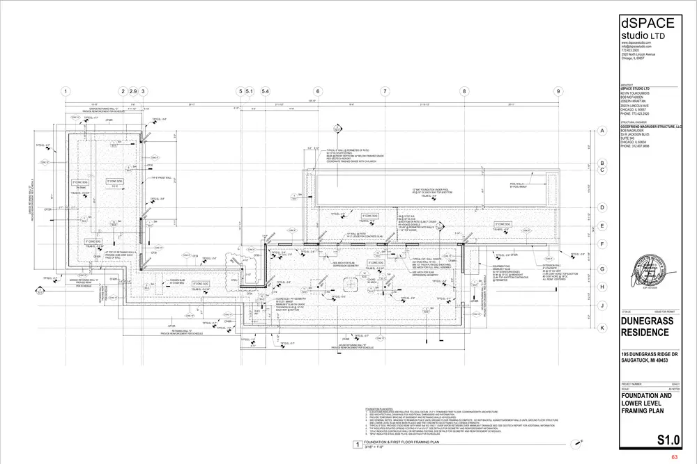
Text of page 63
dSPACE studio LTD www.dspacestudio.com info@dspacestudio.com 773.423.2920 2920 North Lincoln Avenue Chicago, IL 60657
ARCHITECT
2.9 3
5 5.1
5.4
dSPACE STUDIO LTD KEVIN TOUKOUMIDIS BOB MCFADDEN JOSEPH KRAFTAN 2920 N LINCOLN AVE CHICAGO, IL 60657 PHONE: 773.423.2920
135'-10" 15'-10"
5'-6"
GARAGE RETAINING WALL "C" PROVIDE REINFORCEMENT PER SCHEDULE CONC 10"
4'-11 1/2"
26'-11"
21'-3 1/2" 4 1/2"
6 1/2"
T/FTG EL: -0'-7"
6'-5"
18'-6"
21'-10 1/2"
25'-11"
14'-6"
T/FTG EL: -3'-8"
CF54R 1'-10" 10" 1'-10"
STRUCTURAL ENGINEER
8 1/2"
TYPICAL 8" WALL @ PERIMETER OF PATIO W/ CF18 (18"x9"FOOTING) BEAR @ FROST DEPTH MIN 42" BELOW FINISHED GRADE PER GEOTECH REPORT COORDINATE FINISHED GRADE WITH CIVIL/ARCH
CONC 10"
0.5:12
21'-5"
[No Slope]
11 Sim S3.0
T/SLAB EL: -0'-0 3/4"
F4 10 S3.0
T/FTG EL: -0'-7"
CF72R
CF45R
ELEV. PIT
COORD ELEV. PIT GEOMETRY W/ ELEV. MANUF. MINIMUM 6" SLAB ON GRADE THICKNESS W/ #5 @ 12" OC EACH WAY @ BOTTOM
11 Sim S3.0
F4 T/FTG EL: -0'-6"
5'-1 1/2"
T/FTG EL: -2'-8"
54'-6" 5'-0"
1 Sim S3.0
F4 T/FTG EL: -0'-6"
T/FTG EL: -0'-7"
CF48R 1'-7" 10" 1'-7"
3 Sim S3.0 CONC 10"
EXTENSION WALL 8" CONCRETE #5 @ 16" OC VERT (1) #5 CONT HORIZ. TOP & BOTTOM #5 CONT HORIZ @ 18"OC ALL REINF. CENTERED
07.08.25
+/- 6'-1"
T/FTG EL: -1'-2"
RETAINING WALL "D" PROVIDE REINFORCEMENT PER SCHEDULE
T/FTG EL: -1'-2"
K T/FTG EL: -0'-7"
ISSUE FOR PERMIT
DUNEGRASS RESIDENCE
CONC 10"
CF45R T/FTG EL: -0'-7"
6'-11"
EXP 10/31/2026
10"
CONC 10"
CONC 10"
+/- 6'-2"
3'-7"
10"
1'-7"
CONC 10"
Sim
Sim COORD W/ ARCH
1'-5 1/2"
CF24
1 TYP S3.1
SEE ARCH FOR SLAB DEPRESSION GEOMETRY
EQUIPMENT PAD: MINIMUM 6" SLAB W/ 18" DOWNTURN EDGES W/ #4 @ 12" OC @ MIDHEIGHT (2) #4 TOP & BOTTOM CONTINUOUS @ PERIMETER
4'-10 1/2"
T/FTG EL: -2'-8"
CONC 8"
5'-2 1/2"
5" CONC SOG
H BP SS4 1 X4 X1 /4
CF24
1'-5 1/2"
2 S3.0
Sim
6'-2"
14 S3.0
T/FTG EL: -2'-8"
T/FTG EL: -2'-8" CF42R
TYPICAL EXT. WALL CONSTR.: CF48R 2x6 STUD WALL 16" OC MIN 1/2" THICK PLYWOOD SHEATHING SEE ARCH FOR FULL WALL ASSEMBLY
T/SLAB EL: -0'-0 3/4"
THICKEN SLAB AT STAIR BRG
CONC 8"
CONC 10"
5" CONC SOG
SEE ARCH FOR SLAB DEPRESSION GEOMETRY
H BP SS4 4 X4 X1 /4
1'-4" 10" 1'-4"
H BP SS4 2 X4 X3 /8
10 Sim S3.0
4 1/2"
5'-4"
CF42R
5 1/4"
6'-0"
T/FTG EL: -2'-8"
T/FTG EL: -2'-8"
3 1/2"
RETAINING WALL "A" PROVIDE REINF PER SCHEDULE
3 S2.0
GARAGE RETAINING WALL "A" PROVIDE REINF PER SCHEDULE
T/FTG EL: -2'-8" T/FTG EL: -2'-8"
CF30
CONC 10"
T/FTG EL: -0'-7"
8'-7" 3" 9"
CF24
H BP SS4 4 X4 X1 /4
CONC 8"
10" WALL @ PATIO W/ 2" LEDGE FOR CONCRETE SLAB
T/SLAB EL: +0'-9"
CONC 8"
CF30 /4 X1 X4 S4 HS P4 B
1'-4" 10" 1'-4"
CF42R
AT TOP OF RETAINING WALL A PROVIDE (4)#5 CONT EACH FACE OF WALL
5" CONC SOG
H BP SS4 4 X4 X3 /8
10'-6"
5" CONC SOG CONC 10"
#4 @ 12"OC N-S #4 @ 18" OC E-W @ BOTTOM OF PATIO SLAB 2" COVER #4 HOOKED DOWELS 1 12"x36" @ PERIMETER INTO WALLS S2.0 1 1/2" TOP COVER
CONC 8"
3 1/2"
T/SLAB EL: -0'-0 3/4"
5" CONC SOG T/SLAB EL: +0'-9"
H BP SS4 2 X4 X1 /4
1 Sim S3.0
H BP SS4 4 X4 X3 /8
10 Sim S3.0
T/FTG EL: -3'-9"
10'-1 1/2"
3 S3.0
Sim
H BP SS4 1 X4 X1 /4
2'-7"
1'-11"
10"
4 1/2"
T/FTG EL: -3'-8"
33'-5" 2'-7"
12" MAT FOUNDATION UNDER POOL #5 @ 18" OC EACH WAY TOP & BOTTOM T/SLAB EL: -3'-9"
5 Sim S3.0
10'-4 1/2"
POOL WALLS BY POOL MANUF.
H BP SS4 2 X4 X1 /4
CF72R
5" CONC SOG
T/SLAB EL: -0'-0 3/4"
40'-1"
GARAGE RETAINING WALL "D" PROVIDE REINFORCEMENT PER SCHEDULE
TYP 8" FROST WALL
5" CONC SOG
B C
1'-2"
CF30
1'-10"
CONC 8"
5 Sim S3.0
9'-0"
3'-2"
HOUSE RETAINING WALL "C1" PROVIDE REINFORCEMENT PER SCHEDULE
T/FTG EL: -0'-7"
GOODFRIEND MAGRUDER STRUCTURE, LLC BOB MAGRUDER 53 W JACKSON BLVD. SUITE 340 CHICAGO, IL 60604 PHONE: 312.607.9898
6'-11 1/8"
1 Sim S3.0
3'-0"
H BP SS4 2 X4 X1 /4
2 S2.0
HOUSE RETAINING WALL "B" PROVIDE REINFORCEMENT PER SCHEDULE
195 DUNEGRASS RIDGE DR SAUGATUCK, MI 49453
0244.01
PROJECT NUMBER: SCALE:
FOUNDATION AND LOWER LEVEL FRAMING PLAN
FOUNDATION PLAN NOTES 1. ELEVATIONS INDICATED ARE RELATIVE TO LOCAL DATUM: 0'-0" = T/FINISHED FIRST FLOOR. COORDINATEWITH ARCHITECTURE. 2. SEE ARCHITECTURAL DRAWINGS FOR ADDITIONAL DIMENSIONS AND INFORMATION. 3. PROVIDE TEMPORARY BRACING AT BASEMENT AND RETAINING WALLS AS REQUIRED. 4. SEE GENERAL NOTES. BRACING TO REMAIN IN PLACE UNTIL GROUND FLOOR FRAMING IS COMPLETE. DO NOT BACKFILL AGAINST BASEMENT WALLS UNTIL GROUND FLOOR STRUCTURE AND LOWER LEVEL SLAB HAVE BEEN PLACED AND THE CONCRETE HAS ATTAINED FULL DESIGN STRENGTH. 5. TYPICAL 5" SOG: PROVIDE 5"SOG REINF WITH WWF 6x6 W2.1/W2.1 OVER VAPOR RETARDER OVER MINIMUM 6" DRAINAGE BED. SEE GEOTECH REPORT FOR ADDITIONAL INFORMATION. 6. "F4" INDICATES ISOLATED SPREAD FOOTING 4'-0"x4'-0"x12". SEE DETAILS FOR GEOMETRY AND REINFORCEMENT INFORMATION. 7. "CFxx" INDICATES CONTINUOUS WALL OR RETAINING FOOTING. SEE DETAILS FOR GEOMETRY AND REINFORCEMENT SCHEDULES. 8. "BPxx" INDICATES STEEL BASE PLATE. SEE DETAILS FOR SCHEDULES.
FOUNDATION & FIRST FLOOR FRAMING PLAN 3/16" = 1'-0"
AS NOTED
S1.0 63
Page 64
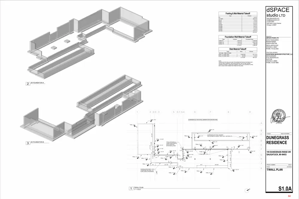
Text of page 64
dSPACE
Footing & Mat Material Takeoff Type
studio LTD
Volume
F4 12" MAT CF16 CF24 CF30 CF42R CF45R CF48R CF54R CF72R
1.8 CY 28.8 CY 1.0 CY 2.7 CY 9.3 CY 6.9 CY 9.9 CY 3.1 CY 3.9 CY 14.6 CY 81.9 CY
www.dspacestudio.com info@dspacestudio.com 773.423.2920 2920 North Lincoln Avenue Chicago, IL 60657
Foundation Wall Material Takeoff Type CONC 8" CONC 10" CONC 14"
Volume 24.8 CY 74.8 CY 12.3 CY 111.9 CY
ARCHITECT
dSPACE STUDIO LTD KEVIN TOUKOUMIDIS BOB MCFADDEN JOSEPH KRAFTAN 2920 N LINCOLN AVE CHICAGO, IL 60657 PHONE: 773.423.2920
Formwork Area 2,029 SF 4,931 SF 568 SF 7,528 SF
Slab Material Takeoff Type Concrete - Slab on Grade Floor: 5" CONC SOG Floor: 6" CONC SOG
Area
Volume
STRUCTURAL ENGINEER 3,049 SF 69 SF 3,118 SF
GOODFRIEND MAGRUDER STRUCTURE, LLC BOB MAGRUDER 53 W JACKSON BLVD. SUITE 340 CHICAGO, IL 60604 PHONE: 312.607.9898
47.1 CY 1.3 CY 48.3 CY
NOTE: SCHEDULES FOR SHALL BE USED FOR ESTIMATION PRICING PURPOSES ONLY. ACTUAL SIZES, GEOMETRY, AND QUANTITIES MAY VARY IN FINAL DESIGN. STEPPED FOOTINGS, LANDSCAPE ELEMENTS, BASE PLATES, BEARING PLATES, BOLTS, AND OTHER CONNECTION ITEMS NOT INCLUDED.
3D FOUNDATION A
2 2.9
5.1 5.4
COORDINATE ALL TOP OF WALL GEOMETRY WITH ARCHITECTURE
T/WALL: 10'-3"
T/WALL: 10'-3"
27'-3 7/8"
T/WALL: 0'-4"
B C
COORDINATE WITH POOL DESIGNER POOL GEOMETRY,LEDGES, T/WALL ELEV., NOTCHES, ETC.
T/WALL: 0'-4"
T/WALL: 0'-4"
T/WALL: 0'-4"
T/WALL: 0'-4"
T/WALL: -1'-0 13/16"
T/CONC @ BP = 0'-4"
T/WALL: 4'-6"
10'-7"
26'-6 5/8"
T/WALL: 11'-7 1/2"
2 1/8"
T/WALL: 10'-7"
0244.01
PROJECT NUMBER: SCALE:
T/WALL: 7'-0"
AS NOTED
T/WALL PLAN
T/WALL: 10'-2 1/2"
T/WALL PLAN 1" = 10'-0"
195 DUNEGRASS RIDGE DR SAUGATUCK, MI 49453
T/WALL: 10'-2 1/2" T/WALL: 11'-7 1/2"
DUNEGRASS RESIDENCE
1'-0"
26'-1 7/8"
T/LEDGE @ HIGH POINT = 10'-0" T/LEDGER @ LOW POINT = 9'-7" SLOPE LEDGE FOR DRAINAGE
8'-0 3/4"
T/WALL: -0'-2 1/4"
T/WALL: 11'-7 1/2" 5"
6'-3"
T/WALL: 0'-4"
T/WALL: 0'-4"
5'-8"
7'-5 1/8"
T/Ledge: -0'-7 3/4"
ISSUE FOR PERMIT
6" 2" 2" T/Ledge: -0'-7 3/4"
T/WALL: 11'-7 1/2"
T/WALL: -0'-2 1/4"
07.08.25
3'-3"
7'-2 1/4"
3 1/2" 2"
1'-0"
11"
1'-2"
1'-0"
1'-0"
11"
T/WALL: 11'-7 1/2"
T/Ledge: -0'-7 3/4"
11"
T/WALL: 10'-5"
T/Ledge: 0'-4"
3 1/2"
T/WALL: -0'-2 1/4"
T/WALL: -0'-2 1/4"
T/WALL: 11'-7 1/2"
1'-0 1/2"
4'-3"
T/WALL: -0'-7 3/4" 2"
T/WALL: 0'-11 3/4" 11"
T/WALL: -0'-2 1/4"
T/WALL: 0'-4"
TYPICAL BP BEARS @ LOWER LEDGE HEIGHTS & SOLID GROUTED AFTER INSTALLATION
11"
2'-11 1/2" 2'-10 5/8"
3D FOUNDATION B
EXP 10/31/2026
S1.0A 64
Page 65
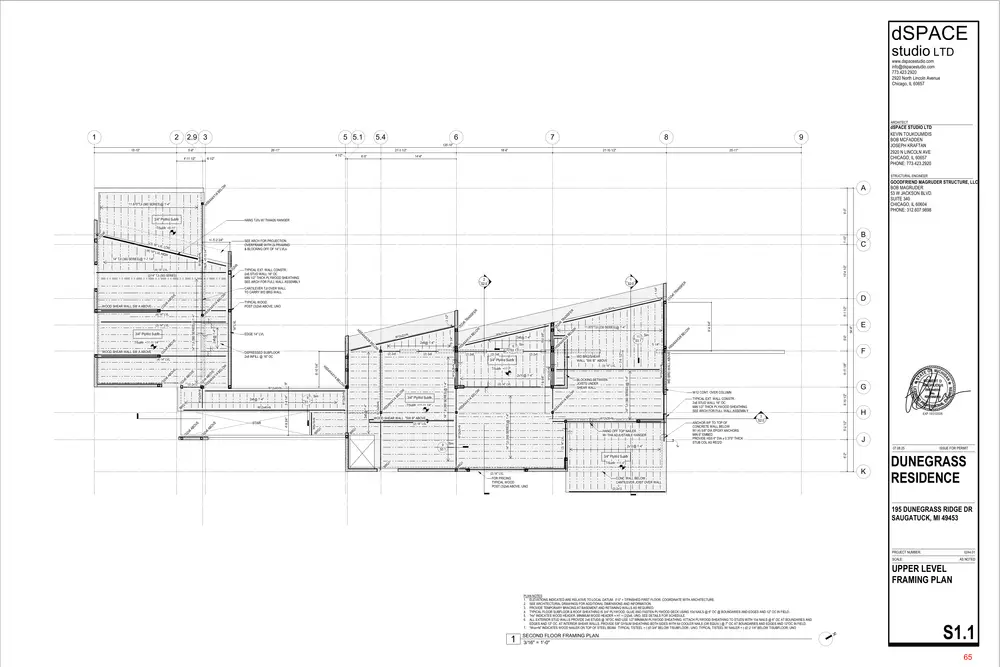
Text of page 65
dSPACE studio LTD www.dspacestudio.com info@dspacestudio.com 773.423.2920 2920 North Lincoln Avenue Chicago, IL 60657
ARCHITECT
2.9 3
5 5.1
5.4
dSPACE STUDIO LTD KEVIN TOUKOUMIDIS BOB MCFADDEN JOSEPH KRAFTAN 2920 N LINCOLN AVE CHICAGO, IL 60657 PHONE: 773.423.2920
135'-10" 15'-10"
5'-6"
26'-11"
4'-11 1/2"
21'-3 1/2" 4 1/2"
6 1/2"
18'-6"
6'-5"
21'-10 1/2"
25'-11"
14'-6"
STRUCTURAL ENGINEER
HS S4 X4 X1 /4
BE LO W
A 9'-0"
11.875"TJI (560 SERIES) @ 1'-4"
3/4" PlyWd Subflr
GOODFRIEND MAGRUDER STRUCTURE, LLC BOB MAGRUDER 53 W JACKSON BLVD. SUITE 340 CHICAGO, IL 60604 PHONE: 312.607.9898
HANG TJI's W/ THA426 HANGER
T/Subflr: +9'-11"
B C
SEE ARCH FOR PROJECTION. OVERFRAME WITH 2x FRAMING & BLOCKING OFF OF 14" LVLs
10'-4 1/2"
2 S2.0
1 S2.0
x6
5'-1 1/2"
BE LO W HS S4 X4 X1 /4 14" TJI (360 SERIES) @ 1'-4"
54'-6" 5'-0"
BE LO W X3 /8
6'-11 1/8"
TYPICAL EXT. WALL CONSTR.: 2x6 STUD WALL 16" OC MIN 1/2" THICK PLYWOOD SHEATHING SEE ARCH FOR FULL WALL ASSEMBLY
W12x26+N
ANCHOR WF TO TOP OF CONCRETE WALL BELOW W/ (4) 5/8" DIA EPOXY ANCHORS MIN 6" EMBED PROVIDE HSS 6" DIA x 0.375" THICK STUB COL AS REQ'D
HANG OFF TOP NAILER W/ THA ADJUSTABLE HANGER 2x12 @ 1'-4"
3 S2.0
07.08.25
3/4" PlyWd Subflr BR G1
T/Subflr: +11'-4"
(2) 14" LVL
FOR PRICING TYPICAL WOOD POST (3)2x6 ABOVE, UNO
EXP 10/31/2026
(2) 14" LVL
W12x26+N
9 Sim S3.1
G W12 CONT. OVER COLUMN
4'-10 1/2"
14" TJI (360 SERIES) @ 1'-4"
11'-9 5/8"
BLOCKING BETWEEN JOISTS UNDER SHEAR WALL
BE LO W
(2) 14" LVL
(3) 14" LVL
W12x35+N
W12x26+N (2) 14" LVL
2x10 @ 1'-4"
HS S4 X4 X1 /4
BE LO W HS S4 X4 X1 /4
T/Subflr: +11'-11 1/4"
WOOD SHEAR WALL "SW B" ABOVE
BR G1
4'-9 3/4"
3/4" PlyWd Subflr
BR G1
x6 (3 )2
STAIR
BR W8x18+N G1
x6 (3 )2
AB OV E
AB OV E
W12x40+N
W12x26+N
2x8 @ 1'-4"
9 Sim S3.1
W12x26+N
3'-8 1/4"
W12x26+N
BR G1
2x8 @ 1'-4"
14" TJI (360 SERIES) @ 1'-4"
6'-10 1/4" 9"
(3 )2 x HS 6 A S4 BO X4 VE X1 /4 BE LO W
x6
AB OV E
AB OV E (3 )2
W LO BE
W12x40+N
T/Subflr: +11'-7"
5'-2 1/2"
WD BRG/SHEAR WALL "SW B" ABOVE
6'-2"
(2) 2x8
5 1/4"
WD BRG WALL ABOVE HS S4 X4
BE LO W
x6 (3 )2 6 Sim S3.1 (2) 2x8
11 Sim S3.1
HS S4 X4 X3 /8
5'-0 3/8"
BE LO W (2) 2x8
2x8 @ 1'-4"
11.875"TJI (230 SERIES) @ 1'-4"
9'-4 1/4"
TR AN SF ER
NS FE R TR A x6 (3 )2
(2) 2x8
0+N W 12x3
+/- 3'-6 1/2"
(2) 2x8
HS S4 X4 X1 /4
14" LVL
2 1/2" 9 1/4"
2x8 @ 1'-4"
+N W 8x31
3/4" PlyWd Subflr
(2) 2x12
(3 )2
BE LO W
(3 )2
2+N
/4 X1 X4 S4 HS
x6
W 12x2
DEPRESSED SUBFLOOR 2x8 INFILL @ 16" OC
(4) 14" LVL
(3 )2
WOOD SHEAR WALL SW A ABOVE
x6
T/Subflr: +11'-11 1/4"
EDGE 14" LVL
W LO BE
AB OV E
3/4" PlyWd Subflr
2x8 @ 1'-4"
(3) 14" LVL
/8 X3 X4 S4 HS
14" TJI (560 SERIES) @ 1'-4"
(4) 14" LVL
TYPICAL WOOD POST (3)2x6 ABOVE, UNO
HS S4 X4 X1 /4
AB OV E x6 (3 )2
WOOD SHEAR WALL SW A ABOVE
1 1/4"
CANTILEVER TJI OVER WALL TO CARRY WD BRG WALL
TR AN SF ER
(2)14" TJI (560 SERIES)
TYPICAL EXT. WALL CONSTR.: 2x6 STUD WALL 16" OC MIN 1/2" THICK PLYWOOD SHEATHING SEE ARCH FOR FULL WALL ASSEMBLY
W12x53+N
(4) 14" LVL
x6
14" TJI (360 SERIES) @ 1'-7 1/4"
(5 )2
W18x46+N
LVL LO W L VL H IGH
T/NLR: +9'-10 1/4"
(3) 16" (4) 14"
1'-10"
x6 (5 )2
+/- 5'-2 3/4"
CONC WALL BELOW CANTILEVER JOIST OVER WALL
ISSUE FOR PERMIT
DUNEGRASS RESIDENCE
(2) 2x12
195 DUNEGRASS RIDGE DR SAUGATUCK, MI 49453
0244.01
PROJECT NUMBER: SCALE:
AS NOTED
UPPER LEVEL FRAMING PLAN PLAN NOTES 1. ELEVATIONS INDICATED ARE RELATIVE TO LOCAL DATUM: 0'-0" = T/FINISHED FIRST FLOOR. COORDINATE WITH ARCHITECTURE. 2. SEE ARCHITECTURAL DRAWINGS FOR ADDITIONAL DIMENSIONS AND INFORMATION. 3. PROVIDE TEMPORARY BRACING AT BASEMENT AND RETAINING WALLS AS REQUIRED. 4. TYPICAL FLOOR SUBFLOOR & ROOF SHEATHING IS 3/4" PLYWOOD. GLUE AND FASTEN PLYWOOD DECK USING 10d NAILS @ 6" OC @ BOUNDARIES AND EDGES AND 12" OC IN FIELD. 5. "Hx" INDICATES WOOD HEADER. MINIMUM WOOD HEADER = H1 = (2)2x8, UNO. SEE DETAILS FOR SCHEDULE. 6. ALL EXTERIOR STUD WALLS PROVIDE 2x6 STUDS @ 16"OC AND USE 1/2" MINIMUM PLYWOOD SHEATHING. ATTACH PLYWOOD SHEATHING TO STUDS WITH 10d NAILS @ 6" OC AT BOUNDARIES AND EDGES AND 12" OC. AT INTERIOR SHEAR WALLS, PROVIDE 5/8" GYSUM SHEATHING BOTH SIDES WITH 6d COOLER NAILS (OR EQUIV.) @ 7" OC AT BOUNDARIES AND EDGES AND 12"OC IN FIELD. 7. "Wxx+N" INDICATES WOOD NAILER ON TOP OF STEEL BEAM. TYPICAL T/STEEL = (-)0'-3/4" BELOW T/SUBFLOOR , UNO. TYPICAL T/STEEL W/ NAILER = (-)0'-2 1/4" BELOW T/SUBFLOOR, UNO
SECOND FLOOR FRAMING PLAN 3/16" = 1'-0"
S1.1 65
Page 66
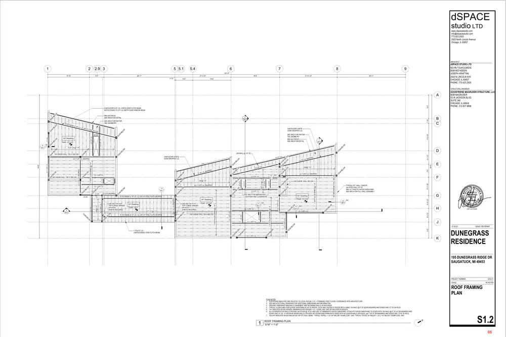
Text of page 66
dSPACE studio LTD www.dspacestudio.com info@dspacestudio.com 773.423.2920 2920 North Lincoln Avenue Chicago, IL 60657
ARCHITECT
2.9 3
5 5.1
5.4
dSPACE STUDIO LTD KEVIN TOUKOUMIDIS BOB MCFADDEN JOSEPH KRAFTAN 2920 N LINCOLN AVE CHICAGO, IL 60657 PHONE: 773.423.2920
135'-10" 15'-10"
5'-6"
26'-11"
21'-3 1/2" 4 1/2"
6'-5"
18'-6"
21'-10 1/2"
25'-11"
14'-6"
STRUCTURAL ENGINEER
9'-0"
TES
(5 )2
SEE ARCH FOR RAFTER TAIL GEOMETRY MIN 2x6 FASCIA SEE ARCH FOR DETAIL
x6 (3 )2
5'-1 1/2"
(3 )2 x6 BE BE LO LO W W
54'-6" 5'-0"
BE LO W
6'-11 1/8"
F TYPICAL EXT. WALL CONSTR.: 2x6 STUD WALL 16" OC MIN 1/2" THICK PLYWOOD SHEATHING SEE ARCH FOR FULL WALL ASSEMBLY
BE LO W
8 Sim S3.1
x6
(3) 11.875" LVL
BE LO W
J (3 )2
x6
BE LO W
x6
07.08.25
(3 )2
x6 (3 )2
BE LO W
BE LO W x6 (3 )2
1.75"x5.5" LVL CANTILEVERED OVER FLITCH BEAM
(3) 11.875" LVL
EXP 10/31/2026
5'-2 1/2"
(3 )2
(3 )2
x6
BE LO W
(2) 11.875" LVL
11 Sim S3.1 (3) 11.875" LVL
11.875"TJI (230 SERIES) @ 1'-4"
BE LO W
(3 )2 x6
(2) 11.875" TJI
WD BRG/SHEAR WALL BELOW
BE LO W
WD SHEAR WALL BELOW
T/Subflr: +23'-6 5/8"
(3 )2
(3 )2
(2) 11.875" LVL DROPPED
x6
(2) 2x10
(2) 2x10
Sim
(2) 11.875" TJI
(2) 2x12
x6
BE LO W
2x8 @ 1'-4"
3/4" Sheathing
11.875"TJI (230 SERIES) @ 1'-4"
11 S3.1
(3) 11.875" LVL
(3 )2
W LO BE
(3 )2
WD SHEAR WALL SW-A BELOW
11.875"TJI (230 SERIES) @ 1'-4"
FLITCH BEAM (3) 14" LVL +(2) 3/8"x14" STEEL PLATE DROPPED
x6
x6
BE LO W
5.5" LVL @ 1'-4"
(3) 14" LVL DROPPED
T/Subflr: +22'-4"
T/Subflr: +23'-6 5/8" USE HGLTV6 H=14" TOP FLANGE HANGER, OR EQUIV. SHIM AS REQUIRED
ED ROPP
x6
(3 )2
SEE ARCH FOR MEP/HEATER LOCATIONS AND CLEARANCES
3/4" Sheathing
x6
)2 (3
BE LO W
(4) 11.875" LVL
2x8 @ 1'-4"
(2) 2x8
3/4" Sheathing
L VL D
(3 )2
x6
(3) 9.25" LVL
FLITCH BEAM (3) 14" LVL +(2) 3/8"x14" STEEL PLATE DROPPED
USE HGLTV6 H=20" TOP FLANGE HANGER, OR EQUIV. SHIM AS REQUIRED
9.25" LVL @ 1'-0"
BE LO W
(2) 2x10
x6 (3 )2
BE LO W
(2) 2x10
BE LO W
x6 BE LO W
(3 )2 (3 )2
x6
(3 )2
(2) 2x10 DROPPED
(2) 2x8
(2) 11.875" LVL DROPPED
(3 )2
x6
x6
BE LO W
12 S3.1
8 Sim S3.1
(3) 9.25" LVL
2x8 @ 1'-4"
(3) 16"
x6
BE LO W x6
D OPPE VL D R
" LVL
(3 )2
(3 )2
5" LVL (3) 9.2
(3 )2
BE LO W
"L (3) 16
x6
(2) 2x12
(2) 2x12
BE LO W
(2) 11.875" TJI
(2) 2x8
3 S2.0
x6
11.875"TJI (230 SERIES) @ 1'-4"
(2) 11.875" TJI
(3) 5.5
BE LO W
CANTILEVER JOISTS OVER DROPPED LVL 2x6
(3 )2
(3) 11.25" LVL DROPPED (3 (3 )2 )2 x6 x6 BE BE LO LO W W
x6
BE LO W
(3) 11.875" LVL
(3 )2
WD SHEAR WALL "SW A" BELOW
2x8 INFILL @ 16" OC
(2) 2x12
x6 (3 )2
BE LO W
BE LO W x6
WD SHEAR WALL "SW A" BELOW
(3 )2
(3 )2
x6
BE LO W
9.25" LVL @ 1'-4"
(3) 11.25" LVL DROPPED
54'-6"
1 S2.0 BE LO W
(2) 9.25" LVL
(2) 9.25" LVL
T/Subflr: +23'-6 5/8"
(3 )2
x6
BE LO W
(2) 2x8
3/4" Sheathing
CANTILEVER JOISTS OVER DROPPED LVL
4'-10 1/2"
EL PL A
6'-2"
3/8"x1 6" STE
BE LO W
(3 )2
BEAM (3) 16" LVL + (2)
B C
1'-10"
SEE ARCH FOR RAFTER TAIL GEOMETRY
(2) 2x8
8 Sim S3.1
2 S2.0
x6
FLITC H
x6
BE LO W
(5 )2
x6
MIN 2x6 FASCIA SEE ARCH FOR DETAIL
10'-4 1/2"
BE LO W
CANTILEVER 9.25" LVL JOISTS OVER FLITCH BEAM NOTCH DOWN TO 5.5" LVL DEPTH OVER WINDOW BEAM
GOODFRIEND MAGRUDER STRUCTURE, LLC BOB MAGRUDER 53 W JACKSON BLVD. SUITE 340 CHICAGO, IL 60604 PHONE: 312.607.9898
ISSUE FOR PERMIT
DUNEGRASS RESIDENCE 195 DUNEGRASS RIDGE DR SAUGATUCK, MI 49453
0244.01
PROJECT NUMBER: SCALE:
AS NOTED
ROOF FRAMING PLAN PLAN NOTES 1. ELEVATIONS INDICATED ARE RELATIVE TO LOCAL DATUM: 0'-0" = T/FINISHED FIRST FLOOR. COORDINATE WITH ARCHITECTURE. 2. SEE ARCHITECTURAL DRAWINGS FOR ADDITIONAL DIMENSIONS AND INFORMATION. 3. PROVIDE TEMPORARY BRACING AT BASEMENT AND RETAINING WALLS AS REQUIRED. 4. TYPICAL FLOOR SUBFLOOR & ROOF SHEATHING IS 3/4" PLYWOOD. GLUE AND FASTEN PLYWOOD DECK USING 10d NAILS @ 6" OC @ BOUNDARIES AND EDGES AND 12" OC IN FIELD. 5. "Hx" INDICATES WOOD HEADER. MINIMUM WOOD HEADER = H1 = (2)2x8, UNO. SEE DETAILS FOR SCHEDULE. 6. ALL EXTERIOR STUD WALLS PROVIDE 2x6 STUDS @ 16"OC AND USE 1/2" MINIMUM PLYWOOD SHEATHING. ATTACH PLYWOOD SHEATHING TO STUDS WITH 10d NAILS @ 6" OC AT BOUNDARIES AND EDGES AND 12" OC. AT INTERIOR SHEAR WALLS, PROVIDE 5/8" GYSUM SHEATHING BOTH SIDES WITH 6d COOLER NAILS (OR EQUIV.) @ 7" OC AT BOUNDARIES AND EDGES AND 12"OC IN FIELD. 7. "Wxx+N" INDICATES WOOD NAILER ON TOP OF STEEL BEAM. TYPICAL T/STEEL = (-)0'-3/4" BELOW T/SUBFLOOR , UNO. TYPICAL T/STEEL W/ NAILER = (-)0'-2 1/4" BELOW T/SUBFLOOR, UNO
ROOF FRAMING PLAN 3/16" = 1'-0"
S1.2 66
Page 67
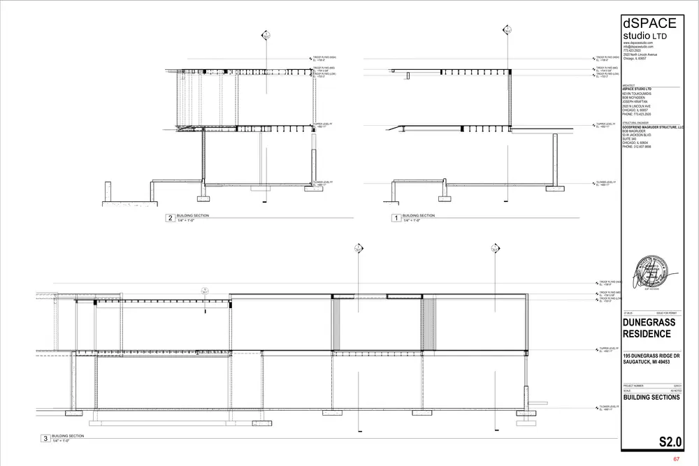
Text of page 67
dSPACE
3 S2.0
studio LTD
3 S2.0
T/ROOF PLYWD (HIGH) EL: +706'-8"
T/ROOF PLYWD (HIGH) EL: +706'-8"
T/ROOF PLYWD (MID) EL: +704'-5 5/8" T/ROOF PLYWD (LOW) EL: +703'-3"
T/ROOF PLYWD (MID) EL: +704'-5 5/8" T/ROOF PLYWD (LOW) EL: +703'-3"
www.dspacestudio.com info@dspacestudio.com 773.423.2920 2920 North Lincoln Avenue Chicago, IL 60657
ARCHITECT
dSPACE STUDIO LTD KEVIN TOUKOUMIDIS BOB MCFADDEN JOSEPH KRAFTAN 2920 N LINCOLN AVE CHICAGO, IL 60657 PHONE: 773.423.2920
T/UPPER LEVEL FF EL: +692'-11"
T/UPPER LEVEL FF EL: +692'-11"
T/LOWER LEVEL FF EL: +680'-11"
T/LOWER LEVEL FF EL: +680'-11"
BUILDING SECTION 1/4" = 1'-0"
2 S2.0
STRUCTURAL ENGINEER
GOODFRIEND MAGRUDER STRUCTURE, LLC BOB MAGRUDER 53 W JACKSON BLVD. SUITE 340 CHICAGO, IL 60604 PHONE: 312.607.9898
BUILDING SECTION 1/4" = 1'-0"
1 S2.0
T/ROOF PLYWD (HIGH) EL: +706'-8" 12 S3.1
EXP 10/31/2026
T/ROOF PLYWD (MID) EL: +704'-5 5/8" T/ROOF PLYWD (LOW) EL: +703'-3"
07.08.25
ISSUE FOR PERMIT
DUNEGRASS RESIDENCE T/UPPER LEVEL FF EL: +692'-11"
195 DUNEGRASS RIDGE DR SAUGATUCK, MI 49453
PROJECT NUMBER: SCALE:
0244.01 AS NOTED
BUILDING SECTIONS T/LOWER LEVEL FF EL: +680'-11"
BUILDING SECTION 1/4" = 1'-0"
S2.0 67
Page 68
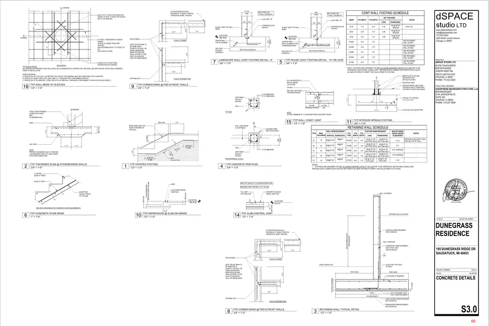
Text of page 68
OPENING 6" TYP UNO
AT DISCONTINUOUS WALL, PROVIDE #4 "U" BARS TO MATCH HORIZONTAL REINF. SPACING
#3x2'-0" EF (4 THUS) FOR SLEEVE DIA UNDER 10" #4 EF (4 THUS) FOR SLEEVE DIA 10" OR GREATER
SEE PLANS FOR T/ WALL GEOMETRY
EQ
0" 1' -
~3'-0"
ELEVATION SEE PLAN PLAN AT CORNER
NOTE: SPLICE BARS TO BE SAME SIZE & QUANTITY AS WALL OR GRADE BEAM BARS BEING SPLICED AND SHALL EXTEND TO FAR FACE OF ADJACENT WALL OR GRADE BEAM
SEE CONT FOOTING SCHEDULE
TYP SLEEVE NOTES: ALL SLEEVES OR OPENINGS THRU WALL SHALL BE COORDINATED BY CONTRACTOR AND SHALL BE APPROVED BY STRUCTURAL ENGINEER PRIOR TO INSTALLATION
SUPPORT BAR FOR PLACEMENT,IF NO TRANSVERSE REINF.
SEE PLAN & SCHEDULE
SEE PLAN & SCHEDULE
SEE CONT FTG SCHEDULE
LANDSCAPE WALL CONT FOOTING DETAIL - 6" 3/4" = 1'-0"
TYP HOUSE CONT FOOTING DETAIL - 10" OR LESS 3/4" = 1'-0"
OPTIONAL KEY
TYP WALL REINF AT SLEEVES 1/2" = 1'-0"
FTG DEPTH
NOTES LONG
TRANSVERSE
1'-4"
0'-9"
2 #5
#3 @ 48"OC SPACER
SITE FTG
CF24
2'-0"
1'-0"
3 #5
#3 @ 48"OC SPACER
CF30
2'-6"
1'-0"
3 #5
#3 @ 48"OC SPACER
CF42R
3'-5"
1'-0"
SEE RETAINING WALL SCHED.
CF45R
3'-9"
1'-0"
SEE RETAINING WALL SCHED.
CF48R
4'-0"
1'-0"
SEE RETAINING WALL SCHED.
CF54R
4'-6"
1'-0"
SEE RETAINING WALL SCHED.
CF72R
6'-0"
1'-0"
SEE RETAINING WALL SCHED.
PVC WATERSTOP AT BELOW GRADE LOCATIONS
TYP CORNER BARS @ FND & FROST WALLS 3/4" = 1'-0"
SLAB ON GRADE, SEE PLANS THICKEN SLAB AT DEPRESSED FOOTINGS WHERE APPLICABLE
2X4 KEY
2" CVR @#6 BARS 1.5" CVR @#5 BARS
CP xx
BEARING
2'-0" MIN LAP
TYP PIER
NOTE: ALLOW A MINIMUM OF 12 HOURS BETWEEN ADJACENT POURS
1'-0"
VR 3" C P TY
30 dB OR 18" MIN
TYP THICKENED SLAB @ STAIR/BEARING WALLS 3/4" = 1'-0"
TYPE
" 1'-0
30 dB OR 18" MIN
WALL REINFORCEMENT WALL FTG THICKNESS VERTICAL HORIZONTAL TYPE
#5@18"
10"
#5@16" OC
10"
#5@16" OC
10"
#5@16" OC
#5@18"
"C1"
10"
#5@16" OC
#5@18"
10"
#5@6" OC
#5@18"
#5@18"
FOOTING REINFORCEMENT FTG FTG WIDTH DEPTH
2" CVR @#6 BARS
VERT REINF EQUALLY SPACED
NEAT EXCAVATION
PIER INTERGRAL w/ WALL
TYP CONCRETE PIER PLAN 3/4" = 1'-0"
LONG
TRANSVERSE
MAX RETAINED HEIGHT ABOVE SLAB/GRADE
NOTES
CF42R
3'-6"
1'-0"
#5 @ 12" OC #4 @18" OC BOTTOM ONLY BOTTOM ONLY
11'-0"
PROVIDE (2) #5 CONT. EACH FACE @ TOP OF WALL
CF45R
3'-9"
1'-0"
#5 @ 16" OC #4 @18" OC BOTTOM ONLY BOTTOM ONLY
7'-0"
CF54R
4'-6"
1'-0"
CF48R
4'-0"
1'-0"
CF72R
6'-0"
1'-0"
TIES
TYP STEPPED FOOTING 1/2" = 1'-0"
11 3/4" = 1'-0"
RETAINING WALL SCHEDULE
COLUMN & PIER SEE PLAN & ARCH
SEE PLAN
CP xx
WALL HORZ REINF IS CONTINOUS
2'-0" MAX
1' - 0"
SEE PLAN
REINF SAME SIZE & NO AS BOTTOM BARS OF FND WALL
NOTE: PROVIDE THICKENED SLAB 1'-0" BEYOND LOAD BEARING POINT (2'-0" MIN) COORD WITH STAIR FABRICATOR
TYP INTERIOR SPREAD FOOTING
15 1/2" = 1'-0"
2'-0"
1' - 0"
GOODFRIEND MAGRUDER STRUCTURE, LLC BOB MAGRUDER 53 W JACKSON BLVD. SUITE 340 CHICAGO, IL 60604 PHONE: 312.607.9898
(4) #5 EACH WAY @ BOTTOM
4' - 0"
TYP WALL CONST JOINT
1' - 0"
STRUCTURAL ENGINEER
3" CVR
60 FEET MAXIMUM SPACING
TIES STEEL STAIR STRINGER COORD WITH STAIR MFR OR BEARING WALL
TYPICAL "F4" FOOTING 12" x 4'-0" x 4'-0"
1' - 0"
VERT REINF EQUALLY SPACED
3-#4 CONT
ARCHITECT
dSPACE STUDIO LTD KEVIN TOUKOUMIDIS BOB MCFADDEN JOSEPH KRAFTAN 2920 N LINCOLN AVE CHICAGO, IL 60657 PHONE: 773.423.2920
ISOLATION JOINT
SEE WALL SECTIONS FOR REINFORCING
SEE PLAN
www.dspacestudio.com info@dspacestudio.com 773.423.2920 2920 North Lincoln Avenue Chicago, IL 60657
BASE PLATE & COLUMN SEE BASE PLATE DETAILS & SCHED.
PLAN AT INTERSECTION
WWF
studio LTD
CF16
NOTE: FOOTINGS ARE DESIGNED FOR NET ALLOWABLE BEARING CAPACITY OF 2,000 PSF TO BE VERIFIED BY GEOTECHNIC CONSULTANT. PROVIDE IN-SITU COMPACTION TESTS AT BOTTOM OF ALL NEW FOOTING TO VERIFY THIS VALUE PRIOR TO FOOTING.
~3'-0"
SLEEVE MATERIAL: A. SLEEVE DIA OF 4" OR LESS - NO RESTRICTION, EXCEPT THE MATERIAL MUST BE COMPATIBLE WITH CONCRETE. B. SLEEVE DIA. MORE THAN 4" BUT LESS THAN 10" - STANDARD PIPE CONFORMING ASTM A53. C. SLEEVE DIA 10" OR GREATER - STEEL PIPE WITH 3/8" MIN WALL THICKNESS CONFORMING TO ASTM A53 OR A283 GRADE C.
SPACER BAR FOR PLACEMENT
DOWELS EQ TO VERT BARS INTERRUPTED BY OPENING
ELEVATION A
ELEVATION SEE PLAN
FTG DEPTH
SPLICE BARS
CONTINUOUS 2X4 KEYWAY
#5 @16" VERT TYP WALL REINF
1'-6"
~3'-0"
2' - 0"
CUT WALL HORIZ BARS AT SLEEVE WHERE SLEEVE IS LARGER THAN VERT SPACING, AND ADD BARS EQUAL TO THOSE CUT ON EACH SIDE OF OPNG
CONTINUOUS 2X4 KEYWAY
FTG WIDTH
EQ
FTG DEPTH
~3'-0"
dSPACE
BOTTOM BARS MARK
(2) #4 T&B, TYP
EQ
#4 @18" VERT TYP WALL REINF
CONT WALL FOOTING SCHEDULE
SEE PLANS FOR T/ WALL GEOMETRY
(2) #4 T&B, TYP EQ
OPENING
SEE PLAN
#5 @ 16" OC #5 @14" OC BOTTOM ONLY BOTTOM ONLY #5 @16" OC #5 @ 16" OC BOTTOM ONLY BOTTOM ONLY #5 @14" OC #5 @ 12" OC TOP & BOT TOP & BOT
8'-6" AVERAGE
7'-6" AVERAGE
11'-0"
NOTES: 1. FOOTINGS ARE DESIGNED FOR NET ALLOWABLE BEARING CAPACITY OF 2,000 PSF TO BE VERIFIED BY GEOTECHNIC CONSULTANT. PROVIDE IN-SITU COMPACTION TESTS AT BOTTOM OF ALL NEW FOOTING TO VERIFY THIS VALUE PRIOR TO FOOTING.
MAXIMUM JOINT SPACING 12'-0" OC EW SLAB REINFORCING SEE PLAN
FILL JOINT WITH SEALANT
1 6"
TYP DEPRESSION @ SLAB ON GRADE 1/2" = 1'-0"
EXP 10/31/2026
TYP SLAB CONTROL JOINT 1/2" = 1'-0"
RETAINED SOIL ELEVATION
07.08.25
~3'-0"
MAX RETAINED HEIGHT SEE SCHEDULE
WALL THICKNESS
HORIZONTAL REINFORCEMENT, EACH FACE, UNO SEE SCHEDULE
1'-6"
195 DUNEGRASS RIDGE DR SAUGATUCK, MI 49453
2" CVR
PLAN AT CORNER
NOTE: SPLICE BARS TO BE SAME SIZE & QUANTITY AS WALL OR GRADE BEAM BARS BEING SPLICED AND SHALL EXTEND TO FAR FACE OF ADJACENT WALL OR GRADE BEAM
(2) #5 CONT TOP & BOT OF WALL
FINAL GRADE ELEV.
PROJECT NUMBER: PER PLANS
PER PLANS
~3'-0"
FOOTING WIDTH
AS NOTED
CONCRETE DETAILS
STD. 90 DEGREE HOOK VERT. REINFORCEMENT LONG FOOTING REINFORCEMENT, SEE SCHEDULE
PLAN AT INTERSECTION
TRANSVERSE REINFORCEMENT, SEE SCHEDULE
TYP CORNER BARS @ FND & FROST WALLS 3/4" = 1'-0"
0244.01
3" COVER 10'-9"
OPTIONAL KEY
SCALE:
TOP REINF (IF PRESENT) FOOTING THICKNESS
SPLICE BARS
ISSUE FOR PERMIT
DUNEGRASS RESIDENCE
VERTICAL REINFORCEMENT, SEE SCHEDULE
AT DISCONTINUOUS WALL, PROVIDE #5 "U" BARS TO MATCH HORIZONTAL REINF. SPACING
~3'-0"
ELEVATION EL=X'-X"
~3'-0"
TYP CONCRETE STAIR REINF 1" = 1'-0"
WALL THICKNESS
"D" SEE PLAN
ELEVATION SEE PLAN
1 SEE ARCH DRAWINGS FOR CONCRETE STAIR REQUIREMENTS.
CONCRETE SLAB ON GRADE, SEE PLAN
D/4
SEE PLAN
#4 BOTTOM @ EACH TREAD (12" OC) MIN
SAW CUT SLAB 8 TO 12 HOURS AFTER POUR
WWF
SEE PLAN
#4 @ 12" CONT
SLAB DEPRESSION SEE ARCH DWGS FOR DIM
(1) #4 TOP @ EACH TREAD
RETAINING WALL TYPICAL DETAIL 1/2" = 1'-0"
S3.0 68
Page 69
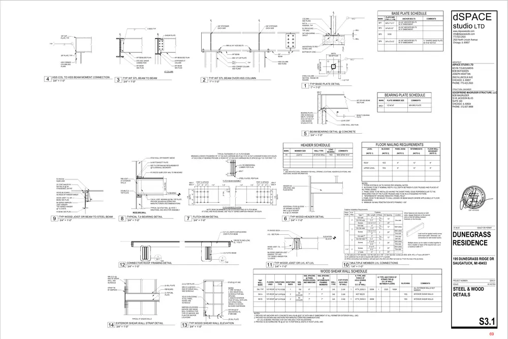
Text of page 69
BASE PLATE SCHEDULE
3/8" STIFFENER EACH SIDE
3 SIDES TYP
COLUMN SEE PLANS NUT & WASHER, TYP
3/8" STIFFENER EACH SIDE
PL PER SCHED TYP, UNO
ANCHOR BOLTS
BP1
5/8"x11"x11"
(4) 3/4" ANCHOR BOLTS W/ 9" EMBEDMENT
BP2
3/4"x6"x12"
(4) 3/4" ANCHOR BOLTS W/ 9" EMBEDMENT
MILL
3/4" NON-SHRINK GROUT
SHEAR PLATE
3/8" CAP PLATE, TYP
PLATE SIZE (THK x L x W)
MARK
1/4
BP3
VOID
BP4
3/4"x12"x12"
MILL
BOTTOM OF CONC
WF BEAM,SEE PLAN
MIN 1/2" CAP PLATE
STD AISC SHEAR CONNECTION
STIFFENER AT COLUMN
1/4 1/4
WF BEAM SEE PLAN
TYP
HSS CORNER COLUMN SEE PLANS
AT COLUMN
TYP WF STL BEAM TO BEAM 3/4" = 1'-0"
STEEL COLUMN SECTION - ROUND OR SQUARE
TYP WF STL BEAM OVER HSS COLUMN 1" = 1'-0"
dSPACE STUDIO LTD KEVIN TOUKOUMIDIS BOB MCFADDEN JOSEPH KRAFTAN 2920 N LINCOLN AVE CHICAGO, IL 60657 PHONE: 773.423.2920
1 1/2" TYP
TYP BASE PLATE DETAIL 1" = 1'-0"
STRUCTURAL ENGINEER
MIN 3"
GOODFRIEND MAGRUDER STRUCTURE, LLC BOB MAGRUDER 53 W JACKSON BLVD. SUITE 340 CHICAGO, IL 60604 PHONE: 312.607.9898
BEARING PLATE SCHEDULE WF OR HSS BEAM SEE PLAN
BEARING PLATE: (SEE SCHEDULE) MIN PL 1/2"X6"X8" W/(2) 3/4" DIA X 4" LONG HEADED STUDS AT 6" OC
MARK
PLATE/ MEMBER SIZE
BRG1
1/2"x6"x8"
COMMENTS
MIN BRG PLATE
BEAM TO BEARING PLATE
(2) #5 CONT CONC WALL, SEE PLAN
BEAM BEARING DETAIL @ CONCRETE 3/4" = 1'-0"
FLOOR NAILING REQUIREMENTS
HEADER SCHEDULE MARK
MEMBER SIZE
WALL TYPE
LOAD BEARING
COMMENTS
H1
(2)2X12
2X STUD WALL
YES
MAX SPAN <6'-0"
TYPICAL FASTENERS AT LVL FLITCH BEAMS: MINIMUM (2) ROWS STAGGERED OF 1/2" DIA A325 CARRIAGE BOLTS @ 12"OC W/ NUT & WASHER IN MAX 9/16" HOLES. AT EACH END AT BEARING PROVIDE (3) ROWS OF 1/2" DIA A325 CARRIAGE BOLTS SPACED @ 4" OC FOR FIRST 1'-0".
LEVEL
BLOCKED
PANEL EDGE
INTERMEDIATE
FLOOR WALL BOUNDARY (NOTE 5)
(NOTE 1)
(NOTE 2)
(NOTE 3)
(NOTE 4)
ROOF
YES
12"
UPPER LEVEL
YES
12"
STUD WALL OR PARAPET ABOVE 2x BOTTOM BOTT PLATE
LVL OR DIMENSIONAL LUMBER, PER PLAN
SEE "FLOOR NAILING REQUIREMENTS" @ FLOOR/WALL BOUNDARY
NOTES: 1. SEE ARCHITECTURAL DRAWINGS FOR WALL OPENING LOCATIONS, HEADER ELEVATIONS, AND ADDITONAL HEADER INFORMATION.
BOLT 3"
PLYWOOD SUBFLOOR, NAIL TO RIM BOARD
WOOD BRG WALL
TYP WOOD JOIST OR BEAM TO STEEL BEAM 3/4" = 1'-0"
1'-0"
1'-0"
1'-0"
TYPICAL TJI BEARING DETAIL 3/4" = 1'-0"
MIN 3" MAX 4"
6" 6"
NOTES: 1. FLOOR SYSTEM IS 3/4" PLYWOOD PER GENERAL NOTES. 2. BLOCKING TO BE 2" NOMINAL WIDTH, FULL DEPTH BETWEEN FLOOR TRUSSES AND PLACED AT ALL PANEL EDGES. 3. PANEL EDGE TO BE INSTALLED HAVING THE SHORT PANEL EDGE PERPENDICULAR TO THE SPAN DIRECTION OF THE FLOOR TRUSSES AND TO BE IN A STAGGERED PATTERN. 4. "INTERMEDIATE" SPACING INDICATES "PANEL FIELD". 5. PANEL EDGE TO BE NAILED TO WALL LEDGER OR BEAM NAILER (WHERE APPLICABLE) AT FLOOR BOUNDARIES. 6. MINIMUM 10d NAIL PENETRATION INTO FRAMING 1-5/8".
HEADER AS SPECIFIEDSEE PLAN NOTES
LVL DEPTH
1'-0"
ADDITIONAL STUDS @ EDGE OF OPENING AS REQ'D MIN (1) @ 2x HEADER & (2) @ LVL HEADER
FLITCH BEAM ELEVATION NOTE; BEAR ON MINIMUM (3) 2x6 STUDS EACH END OF FLITCH BEAM. AT STEEL AND WOOD BEAMS, USE "HGLTV" SERIES SIMPSON HANGER, OR EQUIV.
TYPICAL 2x6 STUD WALL @ 16"OC + SHEATHING, SEE ARCH FOR ASSEMBLY
W BEAM, SEE PLAN
TJI/LVL JOIST, BEARING @ DBL TOP PLATE. PROVIDE SQUASH BLOCKING PER MANUFACTURER'S RECOMMENDATIONS
BA SERIES SIMPSON JOIST HANGER "ITS" SERIES HANGER @ TJI JOISTS
3" TYP
TJI BEARING
WOOD JOIST, TJI, OR BEAM, SEE PLAN
DOUBLE 2x TOP PLATE
FIRST (3) SPACES
2X CONT NAILER W/ 5/8" BOLTS @ 24" STAGGERED, OR PAF WOOD BLOCKING AS REQ'D BY HANGER MANUF.
MIN 3" MAX 4"
STEEL PLATES, PER PLAN FLITCH BEAM ASSEMBLY FIRST (3) SPACES
LVL DEPTH 6" 6"
RIM JOIST AT EXTERIOR WALLS
PLYWOOD SUBFLOOR
SEE PLANS
HSS COL TO HSS BEAM MOMENT CONNECTION 3/4" = 1'-0"
ARCHITECT 1 1/2" TYP
WF BEAM SEE PLAN
1/4
HSS COLUMN SEE PLANS
LENGTH SEE BP PLAN
HSS CORNER COLUMN SEE PLANS
WF BEAM,SEE PLAN
WIDTH SEE BP PLAN
WF BEAM
WF BEAM
3/8" PLATE, TYP
"L" SHAPED BASE PLATE W/ 6"x6" NOTCH
www.dspacestudio.com info@dspacestudio.com 773.423.2920 2920 North Lincoln Avenue Chicago, IL 60657
3" CLR
ANCHOR BOLTS PER SCHED, UNO
dSPACE studio LTD
(4) 3/4" ANCHOR BOLTS W/ 9" EMBEDMENT
TYP
MIN (4) 3/4" A325 BOLTS
COMMENTS
FLITCH BEAM DETAIL 3/4" = 1'-0"
Fastener Installation Requirements
Piece Width
5.5" LVL JOISTS CANTILEVERED OVER FLITCH BEAM
3" 3 ¼"
3(2) 2(2)
Screws 10d nails 12d-16d nails
3 ¾" 8 or 3 ½" 3" 3 ¼" 3 ¾" 8 or 3 ½"
2 3(2) 2(2)
Screws
ELEVATION EL=X'-X"
10d nails (3) 12d-16d nails (3) Screws
7 S3.1 TYP
Screws ½" bolts
BA SERIES SIMPSON JOIST HANGER, TYP UNO "ITS" SERIES HANGER FOR TJI JOISTS
LVL FLITCH BEAM
CONNECTOR ROOF FRAMING DETAIL 3/4" = 1'-0"
10d nails 12d-16d nails
LVL - SEE PLAN
WOOD JOIST, TJI, OR LVL
TYP
T/ROOF PLYWD (LOW) EL: +703'-3"
7 S3.1
Type (1)
TYP WOOD HEADER DETAIL 3/4" = 1'-0"
PLYWOOD DECK
EXP 10/31/2026
Fastener Min. Length # Rows
# of Plies
3" 3 ¼" 5" or 6" 6 ¾" 5" or 6" 6 ¾" 8"
OC Spacing 12"
When fasteners are required on both sides, stagger fasteners on the second side so they fall halfway between fasteners on the first side.
Location One side
24" 12"
Both sides
24"
Both sides One side
3(2) 2(2)
12"
One side (per ply)
24"
24"
24"
07.08.25 Load must be applied evenly across entire beam width. Otherwise, use connections for side-loaded beams.
Both sides
Multiple pieces can be nailed or bolted together to form a header or beam of the required size, up to a maximum width of 7"
One side Both sides
TYP WOOD JOIST OR LVL AT LVL
DUNEGRASS RESIDENCE
One side -
(1) 10d nails are 0.128" diameter; 12d-16d nails are 0.148" - 0.162" diameter; screws are SDS, SDW, WS, or Truss-LOK-EWP™. (2) An additional row of nails is required with depths of 14" or greater. (3) When connecting 4-ply members, nail each ply to the other and offset nail rows by 2" from the rows in the ply below.
MULTIPLE MEMBER LVL CONNECTIONS
11 3/4" = 1'-0"
ISSUE FOR PERMIT
10 1/4" = 1'-0"
195 DUNEGRASS RIDGE DR SAUGATUCK, MI 49453
WOOD SHEAR WALL SCHEDULE MIN (2) 2x @ END OF SHEAR WALL, SEE SCHEDULE
STUDS @ 16" UNO
2x SILL PLATE STRAP TIE BY SIMPSON
RIM BOARD
(2) 2x TOP PLATE MIN (2) 2x @ EACH END OF SHEAR WALL, SEE SCHEDULE
2x TOP DBL PLATE
SOLID 2X BLOCKING AT ALL PANEL EDGES, SEE SCHEDULE
TYPICAL AT SHEAR WALLS
EXTERIOR SHEAR WALL STRAP DETAIL
14 3/4" = 1'-0"
SIMPSON HOLDDOWN ANCHOR, SEE SHEAR WALL SCHEDULE FOR TYPE OF ANCHOR, SEE PLAN FOR ANCHOR LOCATIONS
NOTES 1. USE 10d NAILS. 2. SEE SHEAR WALL SCHEDULE FOR NAIL SPACING. 3. SHEATH EXTERIOR FACE OF WALL WITH APA EXT STRUCTURAL GRADE 2 PLYWOOD, BLOCKED DIAPHRAGM.
5/8" DIA @ 32" ANCHOR BOLTS, 6" MIN EMB 2X SILL PLATE
TYP WOOD SHEAR WALL ELEVATION
13 3/4" = 1'-0"
"SW" WALL MARK
FLOORS SHEATHING SHEATHING USED TYPE SIDES
SW, TYP
1ST-ROOF 1/2" PLY/OSB
SW A
1ST-ROOF 5/8" GYPSUM
SW B
1ST-ROOF 5/8" GYPSUM
NAIL SIZE
10d 6d COOLER 6d COOLER
NAIL SPACING NAIL SPACING @ PANEL @ EDGES,DOORS, INTERMEDIATE AND WINDOWS FRAMING MEMBERS
WALL TYPE
# OF STUDS EACH END OF WALL
2x6
2-2x6
2x6
2-2x6
2x6
2-2x6
#, TYPE, AND FORCE OF HOLD DOWNS @ E.E. OF WALL
HTT4_SDS2.5
#, TYPE, AND FORCE OF STRAPS TIES @ E.E. OF WALL BETWEEN FLOORS
3000#
NOT REQ'D 1
HTT4_SDS2.5
NOTES: 1. PROVIDE 5/8" ANCHORS INTO CONCRETE WALL/SLAB @32" OC WITH MIN 6" EMBEDMENT AT ALL PERIMETER EXTERIOR WALL, UNO. 2. PROVIDE HOLDDOWN AND ANCHORS PER MANUFACTURER RECOMMENDATIONS. -AT LVLs & BEAMS, PROVIDE A 5/8" DIA THRU BOLT FOR HOLDDOWNS. 3. PROVIDE H2.5A HURRICANE TIE @ 32" OC TO RAFTERS & JOISTS AT ROOF LEVEL UNO.
3000#
CS20
0244.01
PROJECT NUMBER:
BLOCKING
COMMENTS
ALL EXTERIOR WALLS NOT MARKED
1000# YES
INTERIOR SHEAR WALLS
YES
INTERIOR SHEAR WALLS
SCALE:
AS NOTED
STEEL & WOOD DETAILS
S3.1 69
Page 70
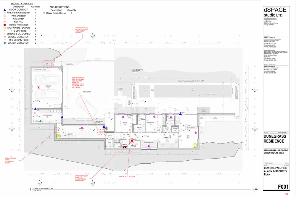
Text of page 70
dSPACE studio LTD www.dspacestudio.com info@dspacestudio.com 773.423.2920 2920 North Lincoln Avenue Chicago, IL 60657
ARCHITECT
dSPACE STUDIO LTD KEVIN TOUKOUMIDIS, BOB MCFADDEN, JOSEPH KAFTAN, LILLIAN JONES, & HAYLEY BURROUGHS
2920 N LINCOLN AVE CHICAGO, IL 60657 PHONE: 773.423.2920 STRUCTURAL ENGINEER
GOODFRIEND MAGRUDER STRUCTURE, LLC BOB MAGRUDER & ERIC WHITE
53 W. JACKSON BLVD. SUITE 340 CHICAGO, IL 60604 PHONE: 312.607.9898 GENERAL CONTRACTOR
ZAHN BUILDERS, INC TONY ZAHN & MATT BRUURSEMA
443 DOUGLAS AVE #40 HOLLAND, MI 49424 PHONE: 616.738.9246
07.08.25
ISSUE FOR PERMIT
DUNEGRASS RESIDENCE 195 DUNEGRASS RIDGE DR SAUGATUCK, MI 49453
PROJECT NUMBER: SCALE:
0244.01 AS NOTED
LOWER LEVEL FIRE ALARM & SECURITY PLAN
F001 70
Page 71
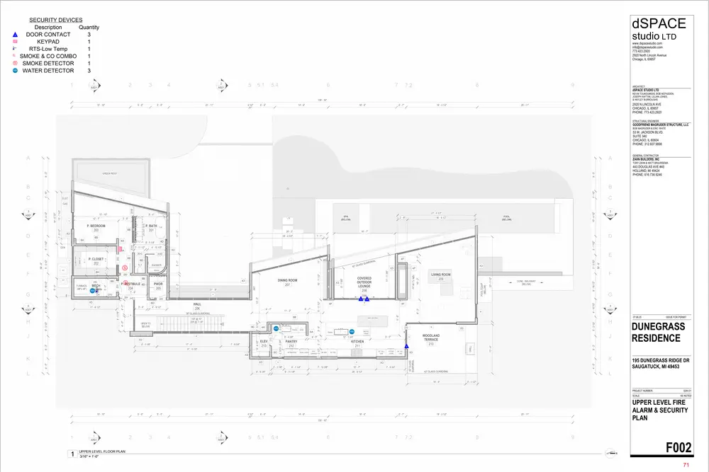
Text of page 71
dSPACE studio LTD www.dspacestudio.com info@dspacestudio.com 773.423.2920 2920 North Lincoln Avenue Chicago, IL 60657
ARCHITECT
dSPACE STUDIO LTD KEVIN TOUKOUMIDIS, BOB MCFADDEN, JOSEPH KAFTAN, LILLIAN JONES, & HAYLEY BURROUGHS
2920 N LINCOLN AVE CHICAGO, IL 60657 PHONE: 773.423.2920 STRUCTURAL ENGINEER
GOODFRIEND MAGRUDER STRUCTURE, LLC BOB MAGRUDER & ERIC WHITE
53 W. JACKSON BLVD. SUITE 340 CHICAGO, IL 60604 PHONE: 312.607.9898 GENERAL CONTRACTOR
ZAHN BUILDERS, INC TONY ZAHN & MATT BRUURSEMA
443 DOUGLAS AVE #40 HOLLAND, MI 49424 PHONE: 616.738.9246
07.08.25
ISSUE FOR PERMIT
DUNEGRASS RESIDENCE 195 DUNEGRASS RIDGE DR SAUGATUCK, MI 49453
PROJECT NUMBER: SCALE:
0244.01 AS NOTED
UPPER LEVEL FIRE ALARM & SECURITY PLAN
F002 71
Page 72
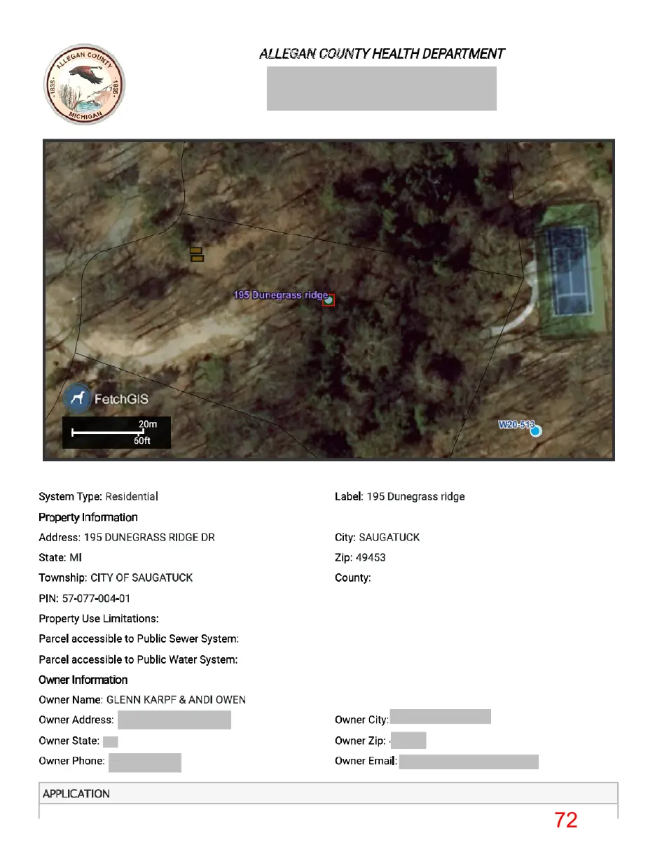
This page is a scanned image with no text layer. The PDF of these pages has it at full resolution.
Page 73
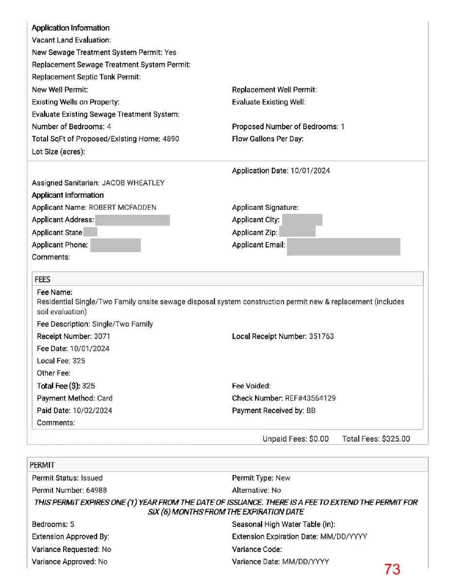
This page is a scanned image with no text layer. The PDF of these pages has it at full resolution.
Page 74
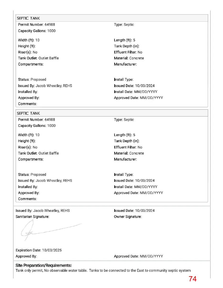
This page is a scanned image with no text layer. The PDF of these pages has it at full resolution.
Page 75
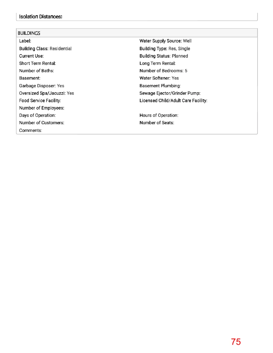
This page is a scanned image with no text layer. The PDF of these pages has it at full resolution.
Page 76
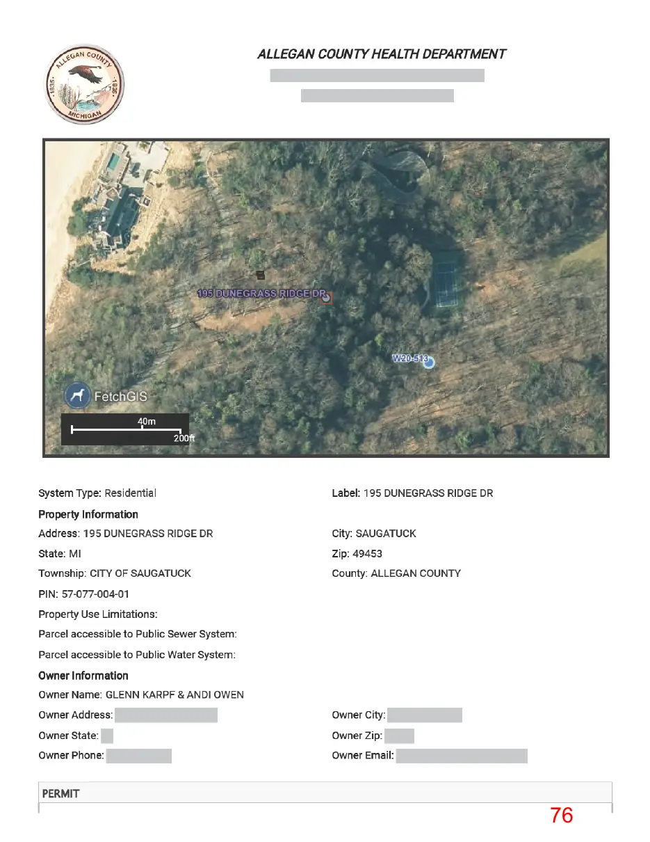
This page is a scanned image with no text layer. The PDF of these pages has it at full resolution.
Page 77
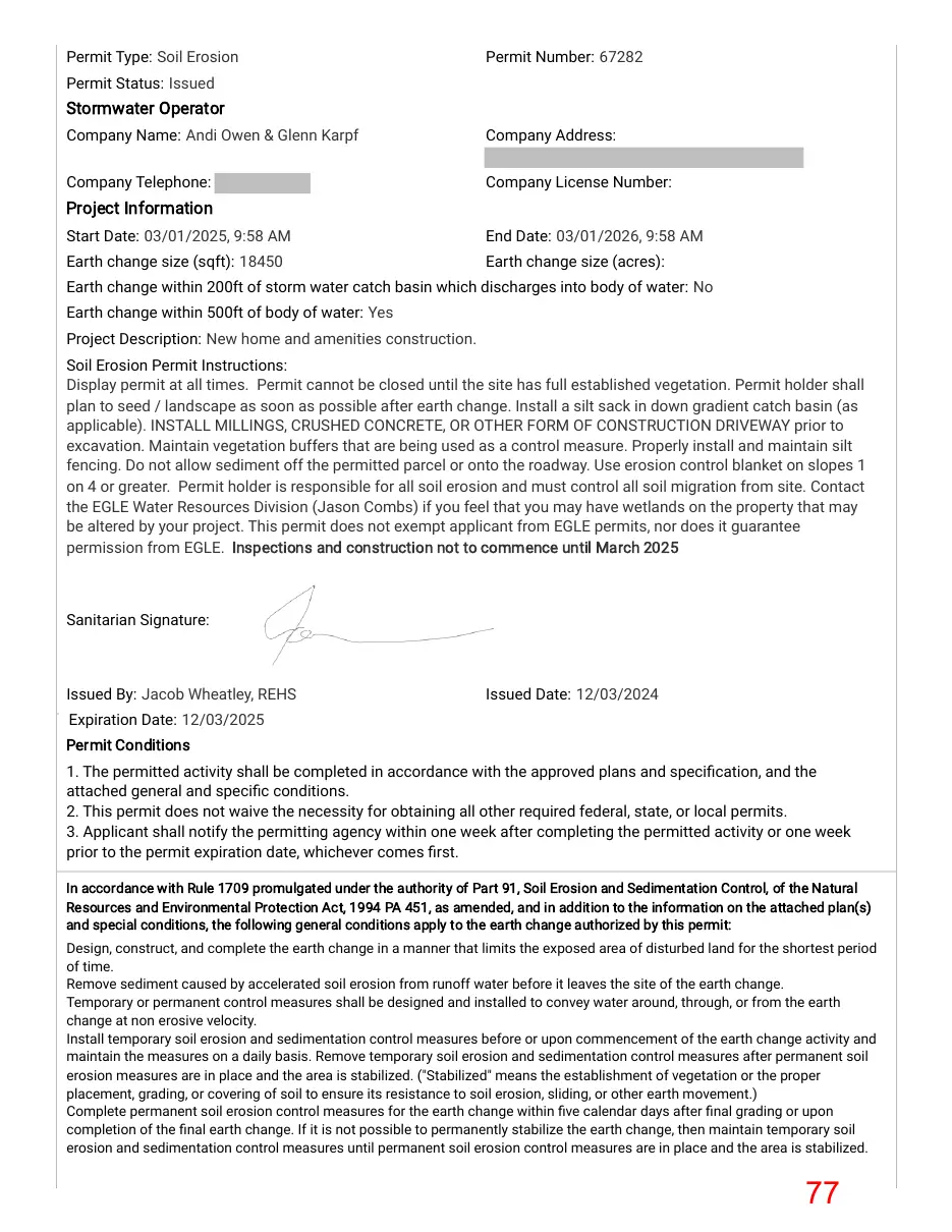
Text of page 77
Permit Type: Soil Erosion
Permit Number: 67282
Permit Status: Issued Stormwater Operator
Company Name: Andi Owen & Glenn Karpf
Company Address:
Company Telephone:
Company License Number:
Project Information
Start Date: 03/01/2025, 9:58 AM
End Date: 03/01/2026, 9:58 AM
Earth change size (sqft): 18450
Earth change size (acres):
Earth change within 200ft of storm water catch basin which discharges into body of water: No Earth change within 500ft of body of water: Yes Project Description: New home and amenities construction. Soil Erosion Permit Instructions: Display permit at all times. Permit cannot be closed until the site has full established vegetation. Permit holder shall plan to seed / landscape as soon as possible after earth change. Install a silt sack in down gradient catch basin (as applicable). INSTALL MILLINGS, CRUSHED CONCRETE, OR OTHER FORM OF CONSTRUCTION DRIVEWAY prior to excavation. Maintain vegetation buffers that are being used as a control measure. Properly install and maintain silt fencing. Do not allow sediment off the permitted parcel or onto the roadway. Use erosion control blanket on slopes 1 on 4 or greater. Permit holder is responsible for all soil erosion and must control all soil migration from site. Contact the EGLE Water Resources Division (Jason Combs) if you feel that you may have wetlands on the property that may be altered by your project. This permit does not exempt applicant from EGLE permits, nor does it guarantee permission from EGLE. Inspections and construction not to commence until March 2025
Sanitarian Signature:
Issued By: Jacob Wheatley, REHS
Issued Date: 12/03/2024
Expiration Date: 12/03/2025 Permit Conditions
1. The permitted activity shall be completed in accordance with the approved plans and specification, and the attached general and specific conditions. 2. This permit does not waive the necessity for obtaining all other required federal, state, or local permits. 3. Applicant shall notify the permitting agency within one week after completing the permitted activity or one week prior to the permit expiration date, whichever comes first. In accordance with Rule 1709 promulgated under the authority of Part 91, Soil Erosion and Sedimentation Control, of the Natural Resources and Environmental Protection Act, 1994 PA 451, as amended, and in addition to the information on the attached plan(s) and special conditions, the following general conditions apply to the earth change authorized by this permit:
Design, construct, and complete the earth change in a manner that limits the exposed area of disturbed land for the shortest period of time. Remove sediment caused by accelerated soil erosion from runoff water before it leaves the site of the earth change. Temporary or permanent control measures shall be designed and installed to convey water around, through, or from the earth change at non erosive velocity. Install temporary soil erosion and sedimentation control measures before or upon commencement of the earth change activity and maintain the measures on a daily basis. Remove temporary soil erosion and sedimentation control measures after permanent soil erosion measures are in place and the area is stabilized. ("Stabilized" means the establishment of vegetation or the proper placement, grading, or covering of soil to ensure its resistance to soil erosion, sliding, or other earth movement.) Complete permanent soil erosion control measures for the earth change within five calendar days after final grading or upon completion of the final earth change. If it is not possible to permanently stabilize the earth change, then maintain temporary soil erosion and sedimentation control measures until permanent soil erosion control measures are in place and the area is stabilized.
Page 78

This page is a scanned image with no text layer. The PDF of these pages has it at full resolution.
Page 79
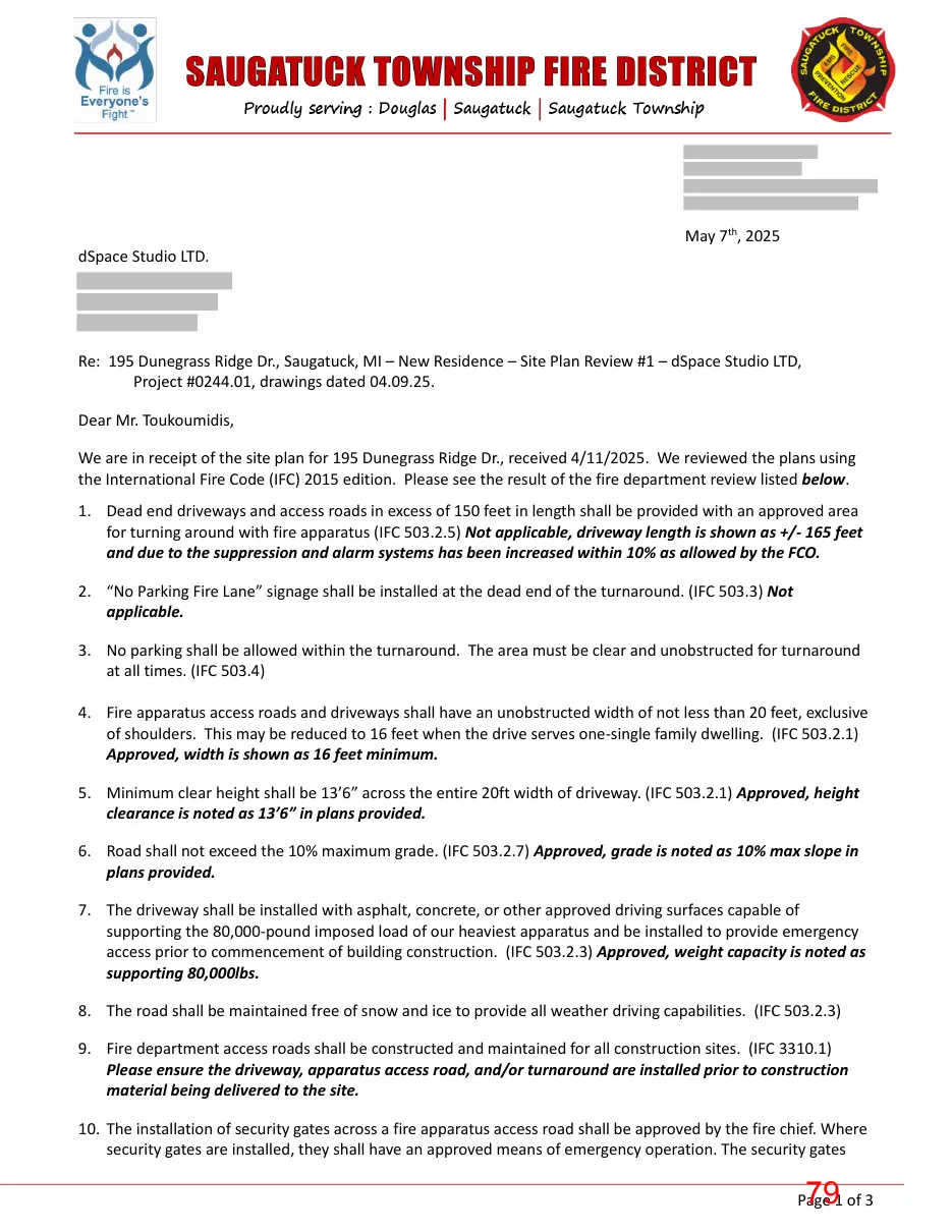
Text of page 79
May 7th, 2025 dSpace Studio LTD.
Re: 195 Dunegrass Ridge Dr., Saugatuck, MI – New Residence – Site Plan Review #1 – dSpace Studio LTD, Project #0244.01, drawings dated 04.09.25. Dear Mr. Toukoumidis, We are in receipt of the site plan for 195 Dunegrass Ridge Dr., received 4/11/2025. We reviewed the plans using the International Fire Code (IFC) 2015 edition. Please see the result of the fire department review listed below. 1. Dead end driveways and access roads in excess of 150 feet in length shall be provided with an approved area for turning around with fire apparatus (IFC 503.2.5) Not applicable, driveway length is shown as +/- 165 feet and due to the suppression and alarm systems has been increased within 10% as allowed by the FCO. 2. “No Parking Fire Lane” signage shall be installed at the dead end of the turnaround. (IFC 503.3) Not applicable. 3. No parking shall be allowed within the turnaround. The area must be clear and unobstructed for turnaround at all times. (IFC 503.4) 4. Fire apparatus access roads and driveways shall have an unobstructed width of not less than 20 feet, exclusive of shoulders. This may be reduced to 16 feet when the drive serves one-single family dwelling. (IFC 503.2.1) Approved, width is shown as 16 feet minimum. 5. Minimum clear height shall be 13’6” across the entire 20ft width of driveway. (IFC 503.2.1) Approved, height clearance is noted as 13’6” in plans provided. 6. Road shall not exceed the 10% maximum grade. (IFC 503.2.7) Approved, grade is noted as 10% max slope in plans provided. 7. The driveway shall be installed with asphalt, concrete, or other approved driving surfaces capable of supporting the 80,000-pound imposed load of our heaviest apparatus and be installed to provide emergency access prior to commencement of building construction. (IFC 503.2.3) Approved, weight capacity is noted as supporting 80,000lbs. 8. The road shall be maintained free of snow and ice to provide all weather driving capabilities. (IFC 503.2.3) 9. Fire department access roads shall be constructed and maintained for all construction sites. (IFC 3310.1) Please ensure the driveway, apparatus access road, and/or turnaround are installed prior to construction material being delivered to the site. 10. The installation of security gates across a fire apparatus access road shall be approved by the fire chief. Where security gates are installed, they shall have an approved means of emergency operation. The security gates
Page 1 of 3
Page 80
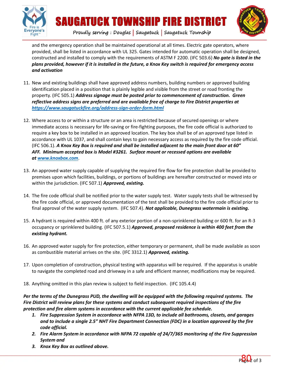
Text of page 80
and the emergency operation shall be maintained operational at all times. Electric gate operators, where provided, shall be listed in accordance with UL 325. Gates intended for automatic operation shall be designed, constructed and installed to comply with the requirements of ASTM F 2200. (IFC 503.6) No gate is listed in the plans provided, however if it is installed in the future, a Knox Key switch is required for emergency access and activation 11. New and existing buildings shall have approved address numbers, building numbers or approved building identification placed in a position that is plainly legible and visible from the street or road fronting the property. (IFC 505.1) Address signage must be posted prior to commencement of construction. Green reflective address signs are preferred and are available free of charge to Fire District properties at https://www.saugatuckfire.org/address-sign-order-form.html 12. Where access to or within a structure or an area is restricted because of secured openings or where immediate access is necessary for life-saving or fire-fighting purposes, the fire code official is authorized to require a key box to be installed in an approved location. The key box shall be of an approved type listed in accordance with UL 1037, and shall contain keys to gain necessary access as required by the fire code official. (IFC 506.1). A Knox Key Box is required and shall be installed adjacent to the main front door at 60” AFF. Minimum accepted box is Model #3261. Surface mount or recessed options are available at www.knoxbox.com. 13. An approved water supply capable of supplying the required fire flow for fire protection shall be provided to premises upon which facilities, buildings, or portions of buildings are hereafter constructed or moved into or within the jurisdiction. (IFC 507.1) Approved, existing. 14. The fire code official shall be notified prior to the water supply test. Water supply tests shall be witnessed by the fire code official, or approved documentation of the test shall be provided to the fire code official prior to final approval of the water supply system. (IFC 507.4). Not applicable, Dunegrass watermain is existing. 15. A hydrant is required within 400 ft. of any exterior portion of a non-sprinklered building or 600 ft. for an R-3 occupancy or sprinklered building. (IFC 507.5.1) Approved, proposed residence is within 400 feet from the existing hydrant. 16. An approved water supply for fire protection, either temporary or permanent, shall be made available as soon as combustible material arrives on the site. (IFC 3312.1) Approved, existing. 17. Upon completion of construction, physical testing with apparatus will be required. If the apparatus is unable to navigate the completed road and driveway in a safe and efficient manner, modifications may be required. 18. Anything omitted in this plan review is subject to field inspection. (IFC 105.4.4) Per the terms of the Dunegrass PUD, the dwelling will be equipped with the following required systems. The Fire District will review plans for these systems and conduct subsequent required inspections of the fire protection and fire alarm systems in accordance with the current applicable fee schedule. 1. Fire Suppression System in accordance with NFPA 13D, to include all bathrooms, closets, and garages and to include a single 2.5” NHT Fire Department Connection (FDC) in a location approved by the fire code official. 2. Fire Alarm System in accordance with NFPA 72 capable of 24/7/365 monitoring of the Fire Suppression System and 3. Knox Key Box as outlined above.
Page 2 of 3
Page 81
Text of page 81
You have site plan approval from the fire department to begin construction 195 Dunegrass Ridge Drive in Saugatuck City if you are in agreement with the above-mentioned items. Please ensure you receive the appropriate permits from Michigan Township Services prior to commencement of construction. Please let us know if you have any questions.
Sincerely, Chris Mantels Deputy Chief / Fire Inspector Cc:
Greg Janik – Fire Chief (via email) Luke Thompson – Zoning Administrator (via email) Dan Poll – Building Official (via email)
Page 3 of 3
Page 82
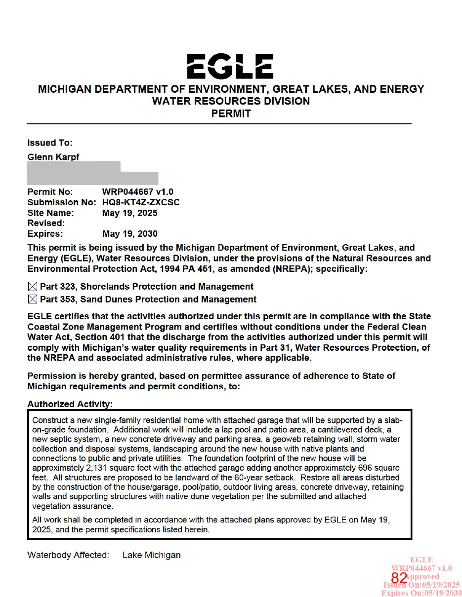
This page is a scanned image with no text layer. The PDF of these pages has it at full resolution.
Page 83
Text of page 83
Glenn Karpf
Waterbody Affected: Property Location:
WRP044667 v1.0
Lake Michigan Allegan County, City of Saugatuck, Town/Range/Section: 03N16W08; Property Tax No: 03-57-077-004-01
Authority granted by this permit is subject to the following limitations: A. Initiation of any work on the permitted project confirms the permittee's acceptance and agreement to comply with all terms and conditions of this permit. B. The permittee, in exercising the authority granted by this permit, shall not cause unlawful pollution as defined by Part 31 of the NREPA. C. This permit shall be kept at the site of the work and available for inspection at all times during the duration of the project or until its date of expiration. D. All work shall be completed in accordance with the approved plans and specifications submitted with the application and/or plans and specifications attached to this permit. E. No attempt shall be made by the permittee to forbid the full and free use by the public of public waters at or adjacent to the structure or work approved. F. It is made a requirement of this permit that the permittee give notice to public utilities in accordance with 2013 PA 174 (Act 174) and comply with each of the requirements of Act 174. G. This permit does not convey property rights in either real estate or material, nor does it authorize any injury to private property or invasion of public or private rights, nor does it waive the necessity of seeking federal assent, all local permits, or complying with other state statutes. H. This permit does not prejudice or limit the right of a riparian owner or other person to institute proceedings in any circuit court of this state when necessary to protect his rights. I. Permittee shall notify EGLE within one week after the completion of the activity authorized by this permit by completing and forwarding the attached preaddressed postcard to the office addressed thereon. J. This permit shall not be assigned or transferred without the written approval of EGLE. K. Failure to comply with conditions of this permit may subject the permittee to revocation of permit and criminal and/or civil action as cited by the specific state act, federal act, and/or rule under which this permit is granted. L. All dredged or excavated materials shall be disposed of in an upland site (outside of floodplains, unless exempt under Part 31 of the NREPA, and wetlands). M. In issuing this permit, EGLE has relied on the information and data that the permittee has provided in connection with the submitted application for permit. If, subsequent to the issuance of a permit, such information and data prove to be false, incomplete, or inaccurate, EGLE may modify, revoke, or suspend the permit, in whole or in part, in accordance with the new information. N. The permittee shall indemnify and hold harmless the State of Michigan and its departments, agencies, officials, employees, agents, and representatives for any and all claims or causes of action arising from acts or omissions of the permittee, or employees, agents, or representative of the permittee, undertaken in connection with this permit. The permittee's obligation to indemnify the State of Michigan applies only if the state: (1) provides the permittee or its designated representative written notice of the claim or cause of action within 30 days after it is received by the state, and (2) consents to the permittee's participation in the proceeding on the claim or cause of action. It does not apply to contested case proceedings under the Administrative Procedures Act, 1969 PA 306, as amended, challenging the permit. This permit shall not be construed as an indemnity by the State of Michigan for the benefit of the permittee or any other person. O. Noncompliance with these terms and conditions and/or the initiation of other regulated activities not specifically authorized shall be cause for the modification, suspension, or revocation of this permit, in whole or in part. Further, EGLE may initiate criminal and/or civil proceedings as may be EGLE WRP044667 v1.0 Approved Issued On:05/19/2025 Expires On:05/19/2030
Page 84
Text of page 84
Glenn Karpf
WRP044667 v1.0
deemed necessary to correct project deficiencies, protect natural resource values, and secure compliance with statutes. P. If any change or deviation from the permitted activity becomes necessary, the permittee shall request, in writing, a revision of the permitted activity from EGLE. Such revision request shall include complete documentation supporting the modification and revised plans detailing the proposed modification. Proposed modifications must be approved, in writing, by EGLE prior to being implemented. Q. This permit may be transferred to another person upon written approval of EGLE. The permittee must submit a written request to EGLE to transfer the permit to the new owner. The new owner must also submit a written request to EGLE to accept transfer. The new owner must agree, in writing, to accept all conditions of the permit. A single letter signed by both parties that includes all the above information may be provided to EGLE. EGLE will review the request and, if approved, will provide written notification to the new owner. R. Prior to initiating permitted construction, the permittee is required to provide a copy of the permit to the contractor(s) for review. The property owner, contractor(s), and any agent involved in exercising the permit are held responsible to ensure that the project is constructed in accordance with all drawings and specifications. The contractor is required to provide a copy of the permit to all subcontractors doing work authorized by the permit. S. Construction must be undertaken and completed during the dry period of the wetland. If the area does not dry out, construction shall be done on equipment mats to prevent compaction of the soil. T. Authority granted by this permit does not waive permit requirements under Part 91, Soil Erosion and Sedimentation Control, of the NREPA, or the need to acquire applicable permits from the County Enforcing Agent (CEA). U. Authority granted by this permit does not waive permit requirements under the authority of Part 305, Natural Rivers, of the NREPA. A Natural Rivers Zoning Permit may be required for construction, land alteration, streambank stabilization, or vegetation removal along or near a natural river. V. The permittee is cautioned that grade changes resulting in increased runoff onto adjacent property is subject to civil damage litigation. W. Unless specifically stated in this permit, construction pads, haul roads, temporary structures, or other structural appurtenances to be placed in a wetland or on bottomland of the water body are not authorized and shall not be constructed unless authorized by a separate permit or permit revision granted in accordance with the applicable law. X. For projects with potential impacts to fish spawning or migration, no work shall occur within fish spawning or migration timelines (i.e., windows) unless otherwise approved in writing by the Michigan Department of Natural Resources, Fisheries Division. Y. Work to be done under authority of this permit is further subject to the following special instructions and specifications: 1. Authority granted by this permit does not waive permit or program requirements under Part 91 of the NREPA or the need to acquire applicable permits from the CEA. To locate the Soil Erosion Program Administrator for your county, visit https://www.michigan.gov/egle/about/organization/water-resources/soil-erosion/sesc-overview and select “Soil Erosion and Sedimentation Control Agencies”. 2. Authority granted by this permit does not waive permit or program requirements under Part 91 of the NREPA or the need to acquire applicable permits from the CEA. To locate the Soil Erosion Program Administrator for your county, visit: EGLE WRP044667 v1.0 Approved Issued On:05/19/2025 Expires On:05/19/2030
Page 85
This page is a scanned image with no text layer. The PDF of these pages has it at full resolution.
Page 86
Text of page 86
Glenn Karpf
WRP044667 v1.0
11. The permittee is responsible for acquiring all necessary easements or rights of way before commencing any work authorized by this permit. All construction operations relating to, or part of this project shall be confined to the existing right-of-way limits or other acquired easements. 12. Prior to the initiation of any permitted construction activities, a sedimentation barrier shall be constructed immediately downgradient of the construction site. Sedimentation barriers shall be specifically designed to handle the sediment type, load, water depth, and flow conditions of each construction site throughout the anticipated time of construction and unstable site conditions. The sedimentation barrier shall be maintained in good working order throughout the duration of the project. Upon project completion, the accumulated materials shall be removed and disposed of at an upland (non-wetland, non-floodplain) site and stabilized with seed and mulch. The sedimentation barrier shall then be removed in its entirety and the area restored to its original configuration and cover. 13. All earth moving and contour changes must occur within five (5) feet of the limits of disturbance as depicted on the attached project drawings. 14. Vegetation changes are not permitted more than ten (10) feet outside of the limits of disturbance as depicted on the attached project drawings. All disturbed areas shall be revegetated with native dune vegetation and stabilized with temporary measures before or upon commencement of the permitted activity and maintained until permanent measures are in place. The removal and re-establishment of vegetation must be in accordance with the submitted and attached vegetation assurance. 15. Restore all areas disturbed by the construction of the house and supporting structures, by planting native species as described in the submitted vegetation assurance. Only native species of plants selected from that attached list are permitted for all site restoration and landscaping around the new house, garage, etc. This will include the planting of new native tree specimens to replace all live trees over a diameter at breast height (DBH) of 3 inches removed as part of this project. The number of replacement trees and their size shall be as described in the attached vegetation assurance. 16. The transport of building materials/excavated sand and access to and from the site shall be via the newly permitted driveway. 17. A separate temporary driveway or access road is not permitted for construction activities. 18. Impacting the dunes is not permitted outside of the approved disturbance area including activities such as driving machinery on any slopes steeper than one-on-three (33%), or storing (permanently or temporarily) machinery, soil, materials, equipment, or removed vegetation, on any slopes steeper than one-on-four (25%). 19. The construction of porches, decks, landscaping (with the exception of planting native dune vegetation), on-grade walkways, on-grade stairways, and retaining walls which also includes the placement of boulders, are considered uses, and not permitted unless specified in the permit conditions. 20. The underground utility lines must be placed in areas with slopes less than one on four or the lines must be installed using the directional bore method or by hand digging. If the directional EGLE WRP044667 v1.0 Approved Issued On:05/19/2025 Expires On:05/19/2030
Page 87
This page is a scanned image with no text layer. The PDF of these pages has it at full resolution.
Page 88
This page is a scanned image with no text layer. The PDF of these pages has it at full resolution.
Page 89

This page is a scanned image with no text layer. The PDF of these pages has it at full resolution.
Page 90
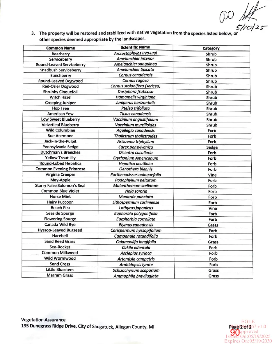
Text of page 90
EGLE WRP044667 v1.0 Approved Issued On:05/19/2025 Expires On:05/19/2030
Page 91
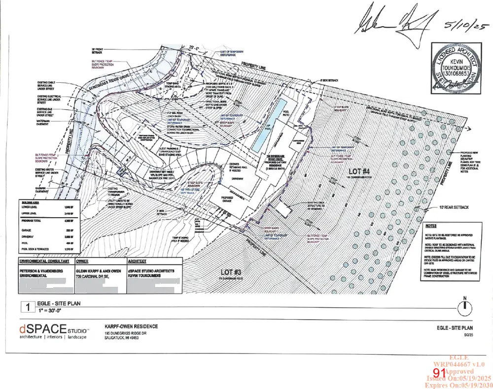
This page is a scanned image with no text layer. The PDF of these pages has it at full resolution.
Page 92
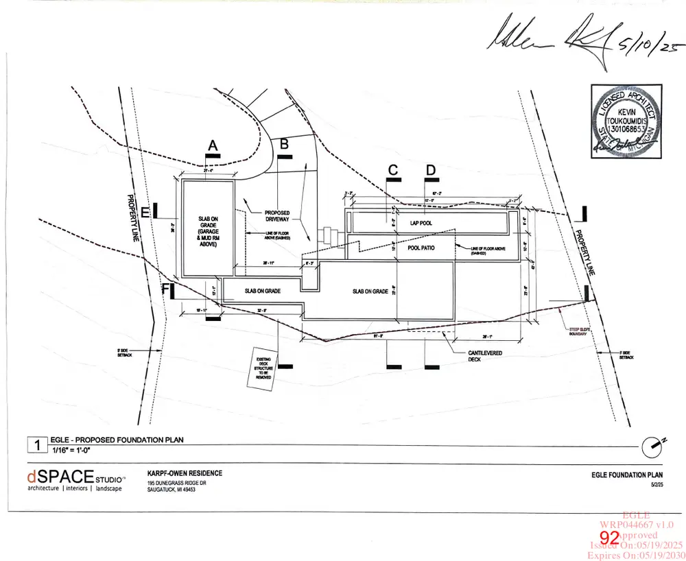
Text of page 92
EGLE WRP044667 v1.0 Approved Issued On:05/19/2025 Expires On:05/19/2030
Page 93
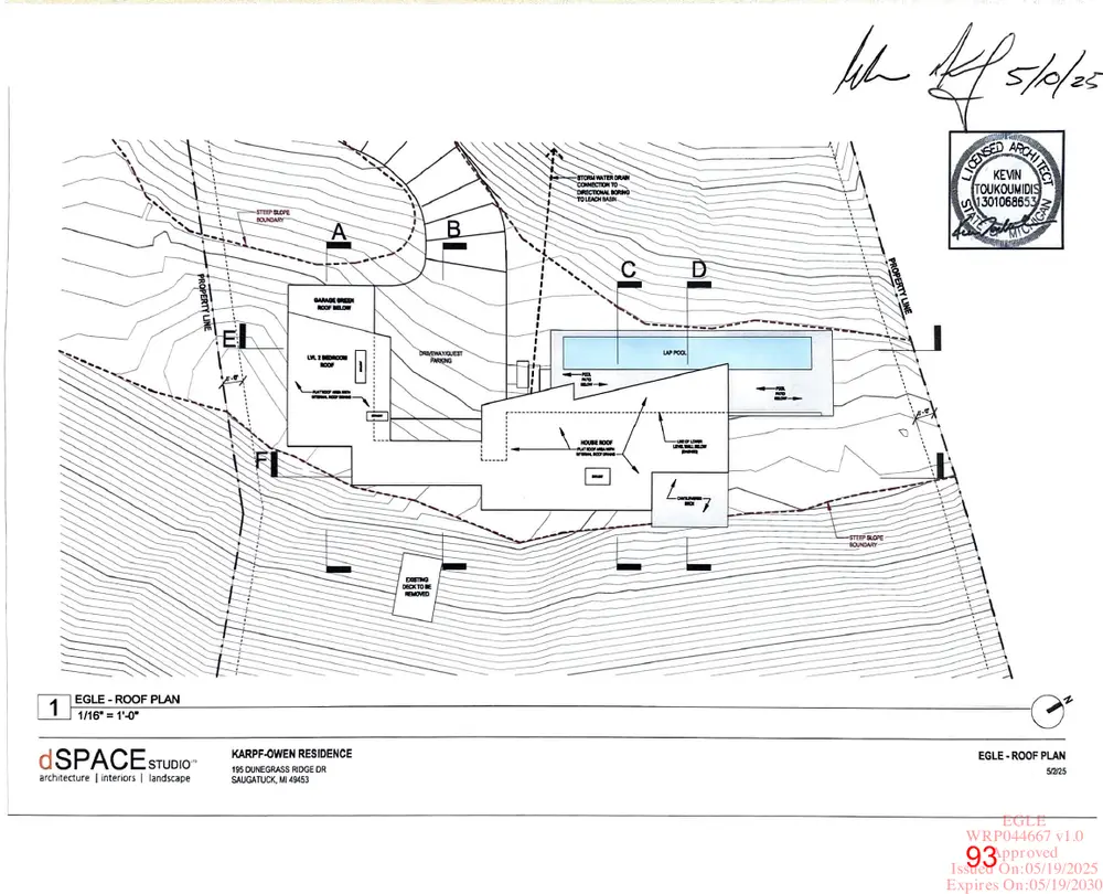
Text of page 93
EGLE WRP044667 v1.0 Approved Issued On:05/19/2025 Expires On:05/19/2030
Page 94
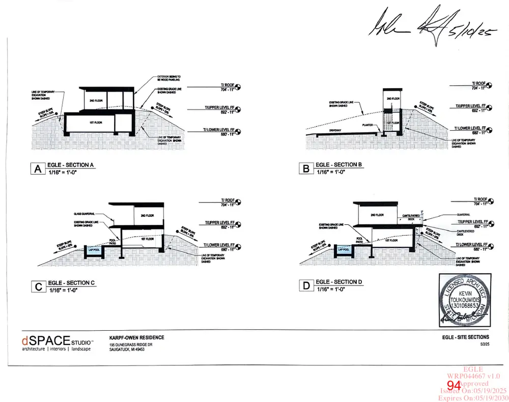
Text of page 94
EGLE WRP044667 v1.0 Approved Issued On:05/19/2025 Expires On:05/19/2030
Page 95
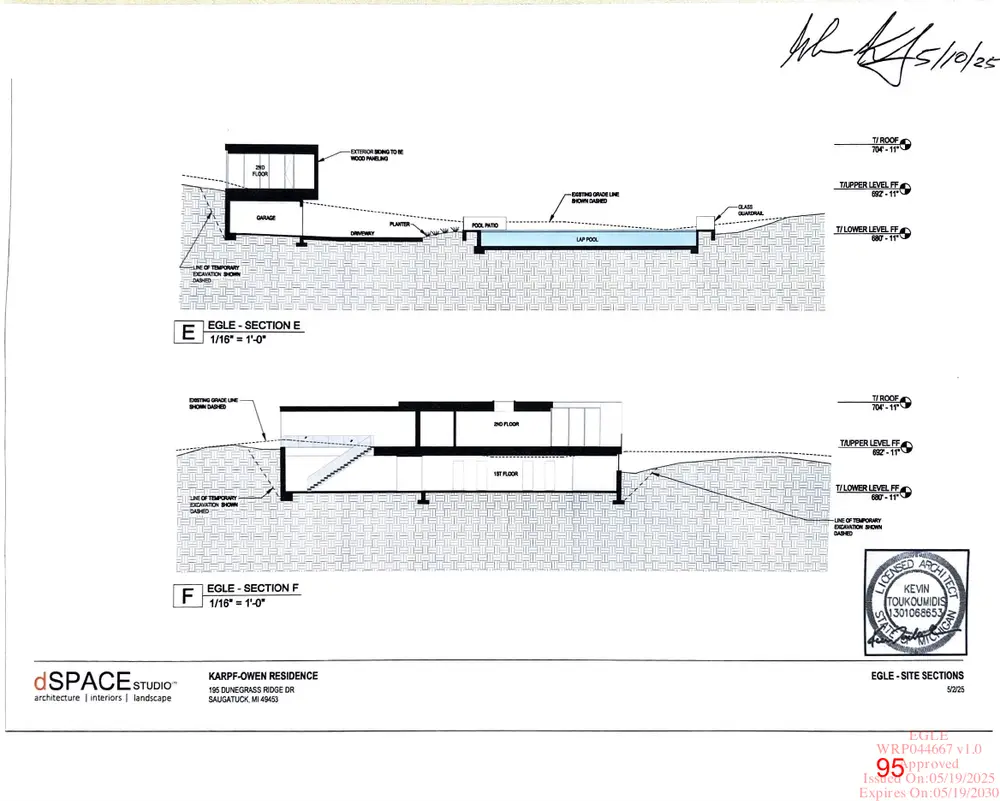
Text of page 95
EGLE WRP044667 v1.0 Approved Issued On:05/19/2025 Expires On:05/19/2030
Page 96
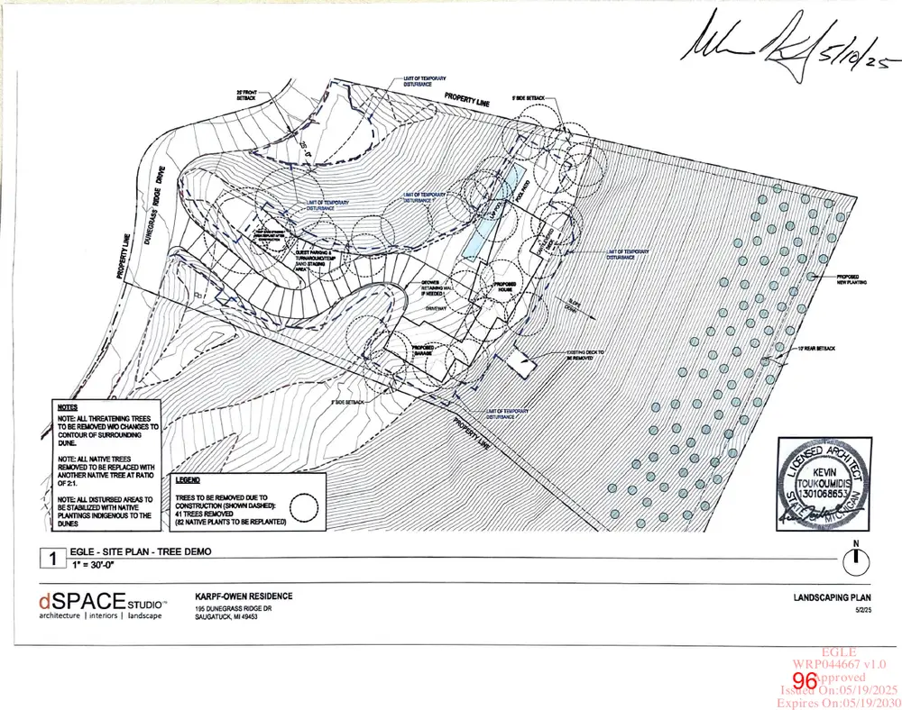
Text of page 96
EGLE WRP044667 v1.0 Approved Issued On:05/19/2025 Expires On:05/19/2030
Page 97
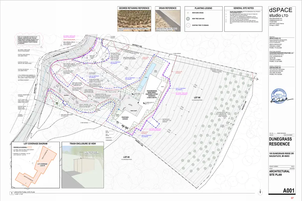
Text of page 97
GEOWEB RETAINING REFERENCE
DRAIN REFERENCE
GENERAL SITE NOTES
PLANTING LEGEND 1.
NEW DUNE GRASS 2. 3.
NEW TREE SAPLING
4. 5. 6.
DO NOT SCALE DRAWINGS. WRITTEN DIMENSIONS HOLD PRIORITY OVER APPARENT SCALE. ALL DIMENSIONS ARE TAKEN FROM THE FACE OF FINISH OR GRIDLINE UNLESS NOTED OTHERWISE. GC TO VERIFY ALL DIMENSIONS & CLEARANCES - NOTIFY ARCHITECT OF ANY DISCREPANCIES PRIOR TO PROCEEDING. REF A703 FOR LIGHT FIXTURE SCHEDULE REF STRUCTURE DRAWINGS FOR STRUCTURAL DETAILS. REF ARCHITECTURAL FLOOR PLAN FOR ADDITIONAL BUILDING INFO.
EXISTING TREE TO REMAIN
PRESTO GEOSYSTEMS - GEOWEB RETAINING WALL SYSTEM
SILT FENCE / TEMP SLOPE PROTECTION BOUNDARY
25' FRONT SETBACK
KEVIN TOUKOUMIDIS, BOB MCFADDEN, JOSEPH KAFTAN, LILLIAN JONES, & HAYLEY BURROUGHS
PROPE
1 E
TEMP SAND STAGING AREA
NEW CURB BOX LABELED FOR 2.5" FIRE SUPPRESSION WATER SERVICE
SL OP
ASPHALT DRIVEWAY: 16FT WIDE & 10% SLOPE MAX PER SAUGATUCK FIRE DEPT
LOT #4 195 DUNEGRASS RIDGE
T/ LOWER LEVEL FF 680' - 11"
ST
EE P SL OP E
GEOWEB RETAINING WALL
NEW TRASH ENCLOSURE W/ WOOD GATE
DRIVE COURT
GREEN ROOF
82 NEW NATIVE TREE SAPLINGS PER APPROVED EGLE PERMIT DRAWINGS.
GASMAIN EASEMENT
SL OP
SILT FENCE / TEMP SLOPE PROTECTION BOUNDARY
2% C TO ROSS GUT S TER LOPE
2% CROSS SLOPE TO GUTTER
T GA
CA BA TCH SIN
T/ POOL PATIO 682' - 2"
0" 16 '-
UTILITY LINES TO BE DIRECTIONALLY BORED UNDER STEEP SLOPE
DRIVEWAY & SITE PLAN APPROVED BY FIRE DEPARTMENT: PLEASE REFERENCE APPROVAL DOCUMENT ON SHEET A/002.
VALLEY GUTTER
DRIVEWAY
195 DUNEGRASS RIDGE DRIVE: PROPOSED 2-STORY RESIDENCE (3 BED/3.5BATH)
VALLEY GUTTER
IN
TT ER
LIMIT OF TEMPORARY DISTURBANCE
GUEST PARKING & TURNAROUND/TEMP SAND STAGING AREA
CH DR A
EXISTING TRANSFORMER TO REMAIN
GU
ST EE P SL OP E
DECK
TR EN
VA LL EY
2'-0" DIA. ROCK LEACH BASIN BELOW NEW CATCH BASIN
NEW 2" DOMESTIC WATER SERVICE & SEPARATE 2.5" FIRE SUPRESSION SERVICE
2% CROS S SLOPE TO GUTT ER
2% CRO SS SLOP E TO GUT TER
P R OP E R
TEMP SAND STAGING AREA: REPLANT AFTER CONSTRUCTION
CA BA TCH SIN
443 DOUGLAS AVE #40 HOLLAND, MI 49424 PHONE: 616.738.9246
POOL
LIMIT OF TEMPORARY DISTURBANCE
STORM WATER DRAIN CONNECTION TO DIRECTIONAL BORING TO LEACH BASIN
TY LINE
30' - 0"
STEEP SLOPE BOUNDARY
TONY ZAHN & MATT BRUURSEMA
68 0
LIMIT OF TEMPORARY DISTURBANCE
WATERMAIN EASEMENT
30' -
POOL PATIO
ZAHN BUILDERS, INC
DIREC TIO FORC NAL BORE EMAIN SEPT DRAIN , TO SHARE IC AGE F IELD D
4'-0" DIA. ROCK LEACH BASIN
11'
2'-0" DIA. ROCK LEACH BASIN BELOW NEW CATCH BASIN
GENERAL CONTRACTOR EE
SL OP
2' TALL ADDRESS SIGN (NUMBERS TO BE 6" TALL): GC TO ENSURE NUMBERS ARE CLEARLY VISIBLE FROM STREET.
EXISTING WATER SERVICE LINE UNDER STREET
ST
EXISTING GAS SERVICE LINE UNDER STREET
53 W. JACKSON BLVD. SUITE 340 CHICAGO, IL 60604 PHONE: 312.607.9898
STEEP SLOPE BOUNDARY
LI N
E W
BOB MAGRUDER & ERIC WHITE
LIMIT OF TEMPORARY DISTURBANCE
EXISTING ELECTRICAL SERVICE LINE UNDER STREET
GOODFRIEND MAGRUDER STRUCTURE, LLC
5' SIDE SETBACK
TY
E DUN
SS GR A
STRUCTURAL ENGINEER
PR O PER
EXISTING CABLE SERVICE LINE UNDER STREET
INE
DIREC T I O NA L TO SH BORE SEP T ARED DRAIN IC FORCEM AIN, AGE F PROPOSED SEPTIC 5' IELD X 8' (1000 GAL) TANKS EACH, 2 FT APART. TANKS ARE MORE DIRECTIONAL BORE ELEC THAN 75 FT FROM TO SEPTIC PUMP CHAMBER CREST OF DUNE
DRIVE E G C RID
2920 N LINCOLN AVE CHICAGO, IL 60657 PHONE: 773.423.2920
PROPOSED GARAGE -
EXISTING DECK STRUCTURE TO BE REMOVED
5' SIDE SETBACK
SILT FENCE / TEMP SLOPE PROTECTION BOUNDARY
RT Y L
ARCHITECT
NEW CURB BOX LABELED FOR 2" DOMESTIC WATER SERVICE
10' REAR SETBACK
GAS METER
LIMIT OF TEMPORARY DISTURBANCE
EE P SL OP E
09.11.25
TRASH ENCLOSURE 3D VIEW
OP E
RT
YL
ISSUE FOR PERMIT
DUNEGRASS RESIDENCE
PR
PERMIT REVISIONS
09.09.25
GENERATOR
CONDENSERS
STEEP SLOPE BOUNDARY
ST
SILT FENCE / TEMP SLOPE PROTECTION BOUNDARY
ELEC METER
LOT COVERAGE DIAGRAM
www.dspacestudio.com info@dspacestudio.com 773.423.2920 2920 North Lincoln Avenue Chicago, IL 60657
dSPACE STUDIO LTD
STEEP SLOPE BOUNDARY
studio LTD
STAINLESS STEEL GRATE TRENCH DRAIN (VEHICULAR GRADE)
NOTE: GC TO RESTORE THE ROAD TO ITS ORIGINAL CONDITION IN ANY LOCATION WHERE REPAIR IS NEEDED FOR NEW UTILITY CONNECTIONS & SITE IMPROVEMENTS. GC TO ALSO COORDINATE TRAFFIC CONTROL AS REQUIRED.
dSPACE
IN E
• PROPOSED LOT COVERAGE =
OR
BE
LO W
• LOT AREA = 66,615 SF (PER 11/05/24 SURVEY) REF. SHEET SP.2 FOR SURVEY
195 DUNEGRASS RIDGE DR SAUGATUCK, MI 49453
LIN E
OF
FLO
• MAXIMUM LOT COVERAGE = 3,331 SF (0.05 × 66,615 SF = 3,331 SF)
4'-0" TALL TRASH ENCLOSURE: CLADDING TO MATCH RESIDENCE
LOT #3 175 DUNEGRASS RIDGE
LOT COVERAGE: 3,262 SF
PROJECT NUMBER:
0244.01
SCALE:
ARCHITECTURAL SITE PLAN OF
FLO
OR
BE
LO W
NIC HE
LIN E
AS NOTED
HB
ARCHITECTURAL SITE PLAN 1/16" = 1'-0"
A001 97
Page 98
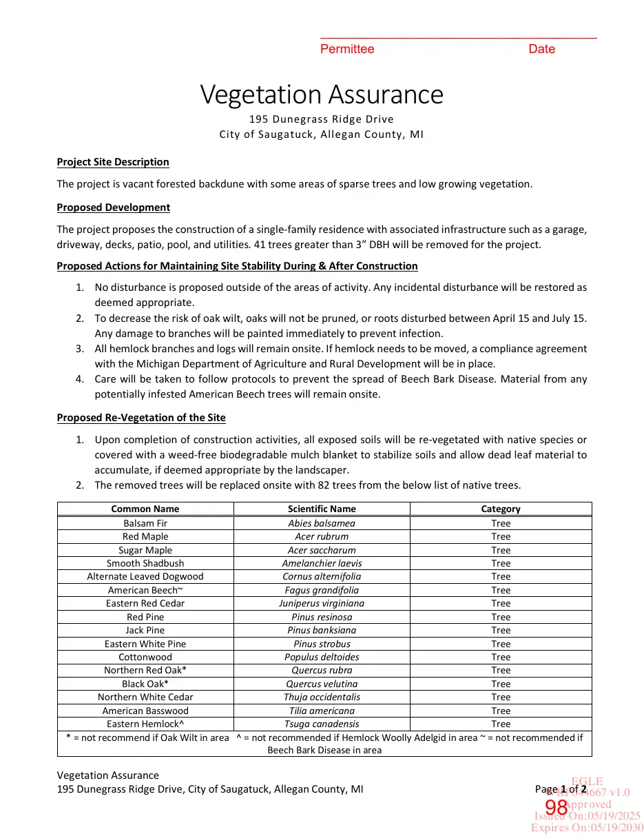
Text of page 98
____________________________________________ Permittee Date
Vegetation Assurance 195 Dunegrass Ridge Drive City of Saugatuck, Allegan County, MI
Project Site Description The project is vacant forested backdune with some areas of sparse trees and low growing vegetation. Proposed Development The project proposes the construction of a single-family residence with associated infrastructure such as a garage, driveway, decks, patio, pool, and utilities. 41 trees greater than 3” DBH will be removed for the project. Proposed Actions for Maintaining Site Stability During & After Construction 1. No disturbance is proposed outside of the areas of activity. Any incidental disturbance will be restored as deemed appropriate. 2. To decrease the risk of oak wilt, oaks will not be pruned, or roots disturbed between April 15 and July 15. Any damage to branches will be painted immediately to prevent infection. 3. All hemlock branches and logs will remain onsite. If hemlock needs to be moved, a compliance agreement with the Michigan Department of Agriculture and Rural Development will be in place. 4. Care will be taken to follow protocols to prevent the spread of Beech Bark Disease. Material from any potentially infested American Beech trees will remain onsite. Proposed Re-Vegetation of the Site 1. Upon completion of construction activities, all exposed soils will be re-vegetated with native species or covered with a weed-free biodegradable mulch blanket to stabilize soils and allow dead leaf material to accumulate, if deemed appropriate by the landscaper. 2. The removed trees will be replaced onsite with 82 trees from the below list of native trees. Common Name Scientific Name Category Balsam Fir Abies balsamea Tree Red Maple Acer rubrum Tree Sugar Maple Acer saccharum Tree Smooth Shadbush Amelanchier laevis Tree Alternate Leaved Dogwood Cornus alternifolia Tree American Beech~ Fagus grandifolia Tree Eastern Red Cedar Juniperus virginiana Tree Red Pine Pinus resinosa Tree Jack Pine Pinus banksiana Tree Eastern White Pine Pinus strobus Tree Cottonwood Populus deltoides Tree Northern Red Oak* Quercus rubra Tree Black Oak* Quercus velutina Tree Northern White Cedar Thuja occidentalis Tree American Basswood Tilia americana Tree Eastern Hemlock^ Tsuga canadensis Tree * = not recommend if Oak Wilt in area ^ = not recommended if Hemlock Woolly Adelgid in area ~ = not recommended if Beech Bark Disease in area
Vegetation Assurance 195 Dunegrass Ridge Drive, City of Saugatuck, Allegan County, MI
EGLE Page 1 of 2 WRP044667 v1.0 Approved Issued On:05/19/2025 Expires On:05/19/2030
Page 99
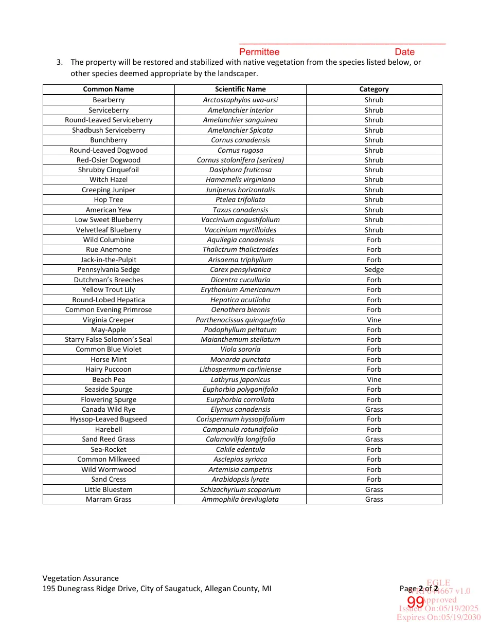
Text of page 99
____________________________________________ Permittee Date
3. The property will be restored and stabilized with native vegetation from the species listed below, or other species deemed appropriate by the landscaper. Common Name Bearberry Serviceberry Round-Leaved Serviceberry Shadbush Serviceberry Bunchberry Round-Leaved Dogwood Red-Osier Dogwood Shrubby Cinquefoil Witch Hazel Creeping Juniper Hop Tree American Yew Low Sweet Blueberry Velvetleaf Blueberry Wild Columbine Rue Anemone Jack-in-the-Pulpit Pennsylvania Sedge Dutchman’s Breeches Yellow Trout Lily Round-Lobed Hepatica Common Evening Primrose Virginia Creeper May-Apple Starry False Solomon’s Seal Common Blue Violet Horse Mint Hairy Puccoon Beach Pea Seaside Spurge Flowering Spurge Canada Wild Rye Hyssop-Leaved Bugseed Harebell Sand Reed Grass Sea-Rocket Common Milkweed Wild Wormwood Sand Cress Little Bluestem Marram Grass
Scientific Name Arctostaphylos uva-ursi Amelanchier interior Amelanchier sanguinea Amelanchier Spicata Cornus canadensis Cornus rugosa Cornus stolonifera (sericea) Dasiphora fruticosa Hamamelis virginiana Juniperus horizontalis Ptelea trifoliata Taxus canadensis Vaccinium angustifolium Vaccinium myrtilloides Aquilegia canadensis Thalictrum thalictroides Arisaema triphyllum Carex pensylvanica Dicentra cucullaria Erythonium Americanum Hepatica acutiloba Oenothera biennis Parthenocissus quinquefolia Podophyllum peltatum Maianthemum stellatum Viola sororia Monarda punctata Lithospermum carliniense Lathyrus japonicus Euphorbia polygonifolia Eurphorbia corrollata Elymus canadensis Corispermum hyssopifolium Campanula rotundifolia Calamovilfa longifolia Cakile edentula Asclepias syriaca Artemisia campetris Arabidopsis lyrate Schizachyrium scoparium Ammophila breviluglata
Vegetation Assurance 195 Dunegrass Ridge Drive, City of Saugatuck, Allegan County, MI
Category Shrub Shrub Shrub Shrub Shrub Shrub Shrub Shrub Shrub Shrub Shrub Shrub Shrub Shrub Forb Forb Forb Sedge Forb Forb Forb Forb Vine Forb Forb Forb Forb Forb Vine Forb Forb Grass Forb Forb Grass Forb Forb Forb Forb Grass Grass
EGLE Page 2 of 2 WRP044667 v1.0 Approved Issued On:05/19/2025 Expires On:05/19/2030
Page 100
Text of page 100
GARY E. MEDLER gary.medler@yahoo.com 461 Vine Street PO Box 461 Saugatuck, Michigan 49453 312-848-2453 September 18, 2025 BY EMAIL DELIVERY
PLANNING COMMISSION
Jamie Wolters City Clerk City of Saugatuck 102 Butler Street/PO Box 86 Saugatuck, Michigan 49453 jwolters@saugatuckcity.com
Steven Manns, Chair Christopher Bagierek, Vice Chair Craig Baldwin Joseph Clark Bobbie Gaunt Mark LaChey Auston Marineau
Grayson Moore Director, Planning and Zoning gmoore@saugatuckcity.com
David M. Jirousek, AICP Consultant
Ryan Cummins City Manager rcummins@saugatuckcity.com Re:
Planning Commission Meeting September 18, 2025; Agenda Item 5B 195 DuneGrass Ridge Dr. – Site Plan Review
Dear Ms. Wolters: This comment letter is submitted for inclusion in the Record on the Site Plan Review Application of the Karph-Owen Family Trust (“Applicant”) for the proposed build at 195 DuneGrass Ridge Drive (“Application”). All residential builds within the DuneGrass Development are subject to: 1. Site plan review pursuant to City Code Sections 154.060 – 154.068;
Page 101
Text of page 101
2. The Consent Judgment in Gary E. Medler v. City of Saugatuck, Planning Commission and City of Saugatuck Zoning Administrator, Case No. 13-52646-CZ, as consolidated with Shorewood Association v. City of Saugatuck and Dune Ridge SA LP, Case No.13-52737AA, entered by the Circuit Court of Allegan County, Allegan, Michigan, on September 24, 2015, recorded December 29, 2015 (“Consent Judgment”); 3.
The Saugatuck Planning Commission Special Land Use Resolution No. 1312203-A, dated December 3, 2013, recorded December 6, 2013 (“SLU Resolution”); and
The Saugatuck City Council Planned Unit Development Resolution 150610-A, dated June 10, 2015 (“PUD Resolution”). Copies of the Consent Judgment, SLU Resolution and PUD Resolution are attached.
This Application has only been reviewed pursuant to the requirements of the City Code and the PUD Resolution (See September 12, 2025, Memorandum contained in the Planning Commission Packet). Until City Staff has evaluated this Application as required by the SLU Resolution and the Consent Judgment, this Application cannot be approved by the Planning Commission. Section 3.8 of the Consent Judgment states: “The SLU Resolution and PUD Resolution and all other resolutions, determinations, decisions and conditions by the City or its departments or designees, and any other government body, agency or official related in any manner to the Property, which were issued or adopted prior to the date of this Consent Judgment remain binding and in effect and are enforceable by the appropriate entity to the extent the resolutions, determinations, decisions and conditions are not inconsistent with this Consent Judgment.” Additionally, paragraph 1 (l) of the PUD Resolution states “Dune Ridge shall abide by verbal representations made at the June 1, 2015 City Council meeting . . .” Despite repeated requests since adoption of the PUD Resolution, the City has yet to memorialize these verbal representations for preservation of the record in order to properly review and evaluate all residential builds since adoption of the PUD Resolution. Once again, I hereby request the City to document these verbal representations and provide copies to all parties to the Consent Judgment.
Page 102
Text of page 102
As presented, this Application has not been fully vetted as required by the Consent Judgment and SLU Resolution and therefore cannot be approved by the Planning Commission. Sincerely
Gary E. Medler cc:
Holly Anderson Lauren Stanton Joseph Clark Scott Dean Russ Gardner Gregory Muncey Chris Peterson
Page 103
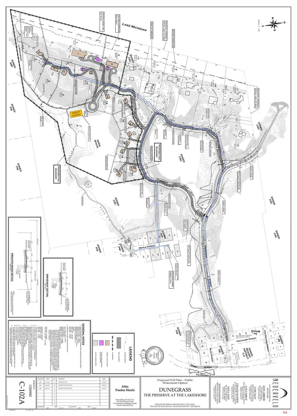
This page is a scanned image with no text layer. The PDF of these pages has it at full resolution.
Page 104
Text of page 104
STATE OF PICHIGAN Allegan County Joyce A. Uatts Register of Deeds RENE
Decettet 06, 2E3 12:41:5t 38C0 Paae 274-324 RESOL FEE: $164 00
1111111111111111 liter
Page 274 #2013026136
I lit PLANNING COMMISSION FOR THE CUT OF SAUGATUCK ALLEGAN COUNTY. MICHIGAN (Resolution No. I31203-A) At a regular meeting of the Planning Commission for the City of Saugatuck held at the City offices on December 3, 2013, beginning at 7:00 p.m., Planning Commission Member Peterson made the motion to adopt the following resolution, which was seconded by Planning Commission Member Schmidt A RESOLUTION APPROVING A SPECIAL LAND USE AND SITE PLAN FOR tab, FORMER PRESBYTERIAN CAMP PROPERTY THE BARKER APPLICATION 13-013) TO BE
DEVELOPED FOR SINGLE-FAMILY RESIDENTIAL HOMES AND TO ATTACH REASONABLE CONDITIONS TO SUCH DEVELOPMENT.
FAc Th For over a hundred years, the Presbytery of Chicago owned and operated a summer camp within the City of Saugatuck (the "City") on and adjacent to Lake Michigan. The property involved is approximately 9L4 acres= in size and is legally described as folloves:
Government Lot 2 F,-,lucling North 400 Ft. Also Government Lot 3 Section 8, Township 3 North, Range 16 West. (the "Overall Property"). To the north of the Overall Property is Oval Beach Park, a property that is owned by the City. A public mad accessing Oval Beach exists across the northern portion of the Property called "Perryman Street". To the south of the Property is a private summer resort association called “Shorewood" According to the Presbytery of Chicago, it is no longer financially feasible for them to operate a summer camp (or a similar use) on the Overall Property. Accordingly, the Overall Property was listed for sale. David Barker (the "Developer") purchased and holds an option to
Page 105
Text of page 105
buy the Overall Property. The Developer hopes to develop 8 single-family residential waterfront parcels or lots from the Overall Property, pursuant to simple metes and bounds land divisions. The portion of the Overall Property to be developed for 8 single-family homes is approximately 22.7 acres in size, has extensive frontage on Lake Michigan, and legally described as follows:
Part of Section 8, Town 3 North, Range 16 West, Village of Saugatuck, Allegan County, Michigan, described as: Commencing at the East 1/4 corner of said Section 8; thence N89°59'16"W 1191.51 feet along the East-West 1/4 line of said Section 8 to the Point of Beginning; thence Southerly 75,38 feet along a 93.00 feet radius curve to the left, the chord of which bears 830°10'35"E 73.33 feet; thence S53°23'43"E 73.10 feet; thence Southerly 40.06 feet along a 20.00 feet radius curve to right, the chord of which bears 503°59'28"W 33.69 feet; thence Southerly 61.95 feet along a 277.00 feet radius curve to the right, the chord of which bears 567°47'04"W 61.82 feet; thence Southerly 56.98 feet along a 162.00 feet radius curve to the right, the chord of which bears S84°16'04"W 56.69 feet; thence N85°39'21"W 166.97 feet; thence Southerly 159.49 feet along a 88.00 feet radius curve to the left, the chord of which bears S42°2520"W 138.54 feet; thence Southerly 43.85 feet along a 37.00 feel radius curve to the right, the chord of which bears 824°27'16"W 41.33 feet; thence Southerly 71.29 feet along a 118.00 feet radius curve to the left, the chord of which bears 541006103"W 70.21 feet; thence 523°47'34"W 20.81 feet; thence Southerly 23.34 fret along a 30.00 feet radius curve to the right, the chord of which bears S46°04'50"W 22.76 feet; thence Southerly 128.54 along a 70.00 feet radius curve to the left, the chord of which bears 515°45'39"W 111.23 feet; thence N67°09'05"W 436.00 feet to Reference Point "A"; thence continuing N67°09'05"W 20 feet more or less to the water's edge of Lake Michigan; thence Northeasterly 1385 feet more or less along said water's edge of Lake Michigan to the intersection of said water's edge of Lake Michigan and a line bearing N89°07'21"Wfrorn Reference Point "B" along the South line of the North 400 feet of the South 1/2 of the Northeast fractional 1/4 of said Section 8 (said Reference Point "B" being located N24°32149"E 1392.13 feet from Reference Point "A"); thence S89°07'.2.1"E 20 feet more or less along said South line to Reference Point "B"; thence continuing S89°0721"E 760.89 feet along said South line; thence Southerly 204.36 fret along a 305.17 feet radius curve right, the chord of which bears 525°06'59"E 200.55 feet; thence SIO°26140"E 61.70 feet; thence Southerly 91.60 feet along a 890.86 feet radius curve to the left, the chord of which bears 514°08'20"E 91.56 feet; thence 589°55'29"W 255.69 feet; thence Southerly 76.08 feet along a 108.00 feet radius curve to the left, the chord of which bears S69°44'42"W 74.51 feet; thence S48 °45'34"W 83.10 feet; thence Southerly 67.05 feet along a 133.00 feet radius curve to the left the chord of which bears 827°31'19"W 66.34 feet; thence 515°20'44"W 128.03 feet; thence 820°11'38"W 183.86 feet; thence Southerly 55.55 feet along a 77.00 feet radius curve to the right, the chord of which bears 540 051'41"W 54.35 feet; thence S61°31'45"W 65.70 feet; thence Southerly 111.16 fret along a 93.00 feet radius curve to the left, the chord of which bears 527°17'09"W 104.70 feet to the Point of Beginning. Contains 23 acres more or less. Subject to easements, restrictions, and rights of way of record.
Page 106
Text of page 106
(the "Residential Property"). The legal descriptions for the proposed individual lots or parcels are as follows: "Lot 5" DESCRIPTION: Part of Section 8, Town 3 North, Range 16 West, Village of Saugatuck, Allegan County, Michigan, described as: Commencing at the East 1/4 corner of said Section 8; thence N89°59'16"W 1191.51 feet along the East-West 1/4 line of said Section 8 to the Point of Beginning; thence Southerly 75.38 feet along a 93.00 feet radius curve to the left, the chord of which bears 530°10'35"E 73.33 feel; thence S53°23`43"E 73.10 feet; thence Southerly 40.06 feet along a 20.00 feet radius curve to right, the chord of which bears S03°59 1.28"W 33.69 feet; thence Southerly 61.95 feel along a 277.00 feet radius curve to the right, the chord of which bears 567°47'04"W 61.82 feet; thence Southerly 56.98 feet along a 162,00 feet radius curve to the right, the chord of which bears S84°16104"Ffl 56.69 feet; thence N85°39'21"W 166.97 feet; thence Southerly 159.49 feet along a 88.00 feet radius curve to the left, the chord of which bears S42°25'20"W 138.54 feet; thence Southerly 43.85 feet along a 37.00 feet radius curve to the right, the chord of which bears 524027'16"W 41.33 feet; thence Southerly 21,70 feet along a 118.00 feet radius curve to the left, the chord of which bears S53 008'2 7"W 21.67 feet to the Point of Beginning; thence Southerly 49.59 feet along a 118.00 feet radius curve to the left, the chord of which bears 533°49'58"W 49,23 feet; thence S23°47'34"W 20.81 feet; thence Southerly 23.34 feet along a 30.00 feet radius curve to the right, the chord of which bears 546°04'50"W 22.76 feet; thence Southerly 128.54 along a 70.00 feet radius curve to the left, the chord of which bears 5150 45'39"W 111,23 feet; thence N67°09'05"W 436.00 feet to Reference Point "1"; thence continuing N67°09105"W 20 feet more or less to the water's edge of Lake Michigan; thence Northeasterly 200 feet more or less along said water's edge of Lake Michigan to the intersection of said water's edge of Lake Michigan and a line bearing N67°07135"W _from Reference Point "2" (said Reference Point "2" being located N24°32 '49"E 200.35 feet from Reference Point"]"),' thence 567°07'35"E 20 feet more or less to Reference Point "2"; thence continuing 867°0735"E 436.72 feet to the Point of Beginning. Contains 2 acres more or less. Subject to easements, restrictions, and rights of way of record. "Lot 6" DESCRIPTION: Part of Section 8, Town 3 North, Range 16 West, Village of Saugatuck, Allegan County, Michigan, described as: Commencing at the East 1/4 corner of said Section 8; thence N89°59'16"W 1191.51 feet along the East-West 1/4 line of said Section 8 to the Point of Beginning; thence Southerly 75.38 feet along a 93.00 feet radius curve to the left, the chord of which bears S30°1035"E 73.33 feet; thence 553°23'43"E 73.10 feet; thence Southerly 40.06 feet along a 20.00 feel radius curve to right, the chord of which bears 503°5928"W 33.69 feet; thence Southerly 61.95 feet along a 277.00 feet radius curve to the right, the chord of which bears S67°47'04"W 61.82 feel; thence Southerly 56.98 feet along a 162.00 feet radius curve to the right, the chord of which bears S84°16'04"W 56.69 feet; thence N85°39'21"W 138.08 feet to the Point of Beginning; thence N85°392 1"W 28.89 feet; thence Southerly 159.49 feet along a 88.00 feet radius curve to the left, the chord of which bears S42025 20"W 138.54 feet; thence Southerly 43.85 feet along a 37.00 feet radius curve to the right, the chord of which bears 824027'16"W 41.33 feet; thence Southerly 21.70 feet along a 118.00 feet radius curve to the left, the chord of which bears 553°08127"W 21.67 feet; thence N67°07135"W 436.72 feet to Reference Point "2"; thence continuing N67°07'35"W 20 feet more or less to the water's edge of Lake Michigan; thence Northeasterly 200 feet more or less along said water's edge of Lake Michigan
Page 107
Text of page 107
to the intersection of said water's edge of Lake Michigan and a line bearing N67°05'38"Wfrom Reference Point "3" (said Reference Point "3" being located N24°32 '49"E 200.15 feet from Reference Point "2'); thence 567°05'38"E 19 feet more or less to Reference Point "3"; thence continuing S67°05'38"E 516,68 feet to the Point of Beginning Contains 2 acres more or less. Subject to easements, restrictions, and rights of way of record.
"Lot 7" DESCRIPTION: Part of Section 8, Town 3 North, Range 16 West, Village of Saugatuck, Allegan County, Michigan, described as: Commencing at the East 1/4 corner of said Section 8; thence N89°59'16"W 1191.51 feet along the East-West 1/4 line of said Section 8; thence Southerly 9.37 feet along a 93.00 feet radius curve to the left, the chord of which bears 809°50'37"E 9.37 feet to the Point of Beginning; thence Southerly 66.01 feet along a 93.00 feet radius curve to the left, the chord of which bears 533 003'45"E 64.63 feet; thence 553 023'43"E 73.10 feet; thence Southerly 40.06 feet along a 20.00 feet radius curve to right, the chord of which bears 503°59128"W 33.69 feet; thence Southerly 61.95 feet along a 277.00 feet radius curve to the right, the chord of which bears S67°47'04"W 61.82 feet; thence Southerly 56.98 feet along a 162.00 feet radius curve to the right, the chord of which bears 584°16'04"W 56.69 feet; thence N85°39'21"W 138.08 feet; thence N67°05'38"W 516.68 feet to Reference Point "3"; thence continuing N67°05'38"W 19 feet more or less to the water's edge of Lake Michigan; thence Northeasterly 200 feet more or less along said water's edge of Lake Michigan to the intersection of said water's edge of Lake Michigan and a line bearing N67°07'35"W from Reference Point "4" (said Reference Point "4" being located N24°32'49"E 200.03 feet from Reference Point "3"2; thence 567°07'35"E 19 feet more or less to Reference Point "4"; thence continuing 367°07'35"E 599.72 feet to the Point of Beginning. Contains 3 acres more or less. Subject to easements, restrictions, and rights of way of record. "Lot 8" DESCRIPTION: Part of Section 8, Town 3 North, Range 16 West, Village of Saugatuck, Allegan County, Michigan, described as: Commencing at the East 1/4 corner of said Section 8; thence N89°59'16"W 1191.51 feet along the East-West 1/4 line of said Section 8 to the Point of Beginning; thence Southerly 9.37 feet along a 93.00 feet radius curve to the left, the chord of which bears 309°50'37"E 9.37; thence N67°07'35 "W 599.72 feet to Reference Point "4"; thence continuing N67°07'35"FV 19 feet more or less to the water's edge of Lake Michigan; thence Northeasterly 200 feet more or less along said water's edge of Lake Michigan to the intersection of said water's edge of Lake Michigan and a line bearing N67°07'08"W from Reference Point "5" (said Reference Point "5" being located N24032'49"E 200.10 feetfrom Reference Point "4"); thence 567°07'08"E 19 feet more or less to Reference Point "5"; thence continuing 567°07'08"E 653.88 feet; thence Southerly 40.19 feet along a 77.00 feet radius curve to the right, the chord of which bears 546°34'42"W 39.74 feet; thence 561031'45"W 65.70 feet; thence Southerly 111.16 feet along a 93.00 feet radius curve to the left, the chord of which bears 327'17'09"W 104.70 feet to the Point of Beginning. Contains 3 acres more or less. Subject to easements, restrictions, and rights of way of record. "Lot 9" DESCRIPTION: Part of Section 8,. Town 3 North, Range 16 West, Village of Saugatuck, Allegan County, Michigan, described as: Commencing at the East 1/4 corner of said Section 8; thence N890 59'16"W 1191.51 feet along the East-West 1/4 line of said Section 8; thence Northerly 111.16 feet along a 93.00 feet radius curve to the right, the chord of which bears N27°17'09"E 104,70 feet; thence N61°31`45"E 65.70 feet; thence Northerly 40.19 feet along a
Page 108
Text of page 108
77.00 feet radius curve to the left, the chord of which bears N46°34'42"E 39.74 feet to the Point of Beginning; thence N67°07'08 "W 653.88 feet to Reference Point "5"; thence continuing N67°07'08"W 19 feet more or less to the water's edge of Lake Michigan; thence Northeasterly 200 feet more or less along said water's edge of Lake Michigan to the intersection of said water's edge of Lake Michigan and a line bearing N67°01'22"W from Reference Point "6" (said Reference Point "6" being located N24°32'49"E 200.13 feet from Reference Point "5'2; thence 567°011.22"E 19 feet more or less to Reference Point "6"; thence continuing S67°01'22"E 640.25 feet; thence S20°11'38"W 183.86 feet; thence Southerly 15.36 feet along a 77.00 feet radius curve to the right, the chord of which bears 525°54'28"W 15.33 feet to the Point of Beginning. Contains 3 acres more or less. Subject to easements, restrictions, and rights of way of record. "Lot 10" DESCRIPTION: Part of Section 8, Town 3 North, Range 16 West, Village of Saugatuck, Allegan County, Michigan, described as: Commencing at the East 1/4 corner of said Section 8; thence N89°59'16"W 1191.51 feet along the East-West 1/4 line of said Section 8 to the Point of Beginning; thence Northerly 111.16 feet along a 93.00 feet radius curve to the right, the chord of which bears N27°1709E 104.70 feet; thence N61°31'45"E 65.70 feet; thence Northerly 55.55 feet along a 77.00 feet radius curve to the left, the chord of which bears N40°51'41"E 54.35 feet; thence N20°11138"E 183.86 feet to the Point of Beginning; thence N67°01`22"W 640.25 feet to Reference Point "6"; thence continuing N67°0122"W 19 feet more or less to the water's edge of Lake Michigan; thence Northeasterly 200 feet more or less along said water's edge of Lake Michigan to the intersection of said water's edge of Lake Michigan and a line bearing N75°07116"W from Reference Point "7" (said Reference Point "7" being being located N24°32'49"E 202.64 feet from Reference Point "6'9; thence S75°07'16"E 19 feet more or less to Reference Point "7"; thence continuing S75007'16"E 493.15 feet; thence S36°38'06"E 156.17 feet; thence Southerly 67.05 feet along a 133.00 feet radius curve to the left, the chord of which bears S27°3119"W 66.34 feet; thence S15°20'44"W 128.03 feet to the Point of Beginning. Contains 3 acres more or less. Subject to easements, restrictions, and rights of way of record. "Lot 11" DESCRIPTION: Part of Section 8, Town 3 North, Range 16 West, Village of Saugatuck, Allegan County, Michigan, described as: Commencing at the East 1/4 corner of said Section 8; thence N89°59'16"W 1191.51 feet along the East-West 1/4 line of said Section 8; thence Northerly 111.16 feet along a 93.00 feet radius curve to the right, the chord of which bears N27°17'09"E 104.70 feet; thence N61031'45"E 65.70 feet; thence Northerly 55.55 feet along a 77.00 feet radius curve to the left, the chord of which bears N40°51'41"E 54.35 feet; thence N20°11 '38"E 183.86 feet; thence N15°20'44"E 128.03 feet; thence Northerly 67.05 feet along a 133.00 feet radius curve to the right, the chord of which bears N27°31`19"E 66.34 feet; thence N36°38'06"W 156.17 feet to the Point of Beginning; thence N75°07 116"W 493.15 feet to Reference Point "7"; thence continuing N75°07'16"W 19 feet more or less to the water's edge of Lake Michigan; thence Northeasterly 200 feet more or less along said water's edge of Lake Michigan to the intersection of said water's edge of Lake Michigan and a line bearing N89°07'21"W from Reference Point "8" along the South line of the North 400 feet of the South 1/2 of the Northeast fractional 1/4 of said Section 8 (said Reference Point "8" being N24°32'49"E 188.75 feet from Reference Point "7'9; thence S89°07'21"E 20 feet more or less along said South line to Reference Point "8"; thence continuing 889°07'21"E 492.48 feet along said South line; thence S17°571.14"W 305.66 feet to the Point of Beginning. Contains 3 acres more or less. Subject to easements, restrictions, and rights of way of record.
Page 109
Text of page 109
"Lot 12" DESCRIPTION: Part of Section 8, Town 3 North, Range 16 West, Village of Saugatuck, Allegan County, Michigan, described as: Commencing at the East 1/4 corner of said Section 8; thence N89°591.16"W 1191.51 feet along the East-West 1/4 line of said Section 8; thence Northerly 111.16 feet along a 93.00 feet radius curve to the right, the chord of which bears N27°17'09"E 104.70 feet; thence N6] °31'45"E 65.70 feet; thence Northerly 55.55 feet along a 77.00 feet radius curve to the left, the chord of which bears N40°5141"E 54.35 feet; thence N20°11'38"E 183.86 feet; thence N15°2044"E 128.03 feet; thence Northerly 67.05 feet along a 133.00 feet radius curve to the right, the chord of which bears N27°31119"E 66.34 feet to the Point of Beginning; thence N36°38106"W 156.17 feet; thence N] 7°57'14"E 305.66 feet; thence S89°07'21"E 268,41 feet along the South line of the North 400 feet of the South 1/2 of the Northeast fractional 1/4 of said Section, 8; thence Southerly 204.36 feet along a 305.17 feet radius curve to the right, the chord of which bears 525°06'59"E 200.55 feet; thence SI0°26'40"E 61.70 feet; thence Southerly 91.60 feet along a 890.86 feet radius curve to the left, the chord of which bears 514°08'20"E 91.56 feet; thence S89°55'29"W 255.69 feet; thence Southerly 76.08 feet along a 108.00 feet radius curve to the left, the chord of which bears 869°44'42"W 74.51 feet; thence 548°45'34"W 83.10 feet to the Point of Beginning. Contains 3.17 acres. Subject to easements, restrictions, and rights of way of record. The balance of the Overall Property, which will remain undeveloped (at least for the foreseeable future), is approximately 68.7 acres in size and is legally described as follows: The South 1/2 of the Northeast fractional 1/4 of Section 8, Town 3 North, Range 16 West, Except the North 400 feet thereof AND ALSO, Government Lot 3, also described as the North _fractional 1/2 of the Southeast _fractional 1/4 of Section 8, Town 3 North, Range 16 West. EXCEPT, "Lots 5-12" DESCRIPTION: Part of Section 8, Town 3 North, Range 16 West, Village of Saugatuck Allegan County, Michigan, described as: Commencing at the East 1/4 corner of said Section 8; thence N89'597 6"W 1191.51 feet along the East-West 1/4 line of said Section 8 to the Point of Beginning; thence Southerly 75.38 feet along a 93.00 feet radius curve to the left, the chord of which bears 530°10'35"E 73.33 feet; thence S53°23'43"E 73.10 feet; thence Southerly 40.06 feet along a 20.00 feel radius curve to right, the chord of which bears 503°59'28"W 33.69 feet; thence Southerly 61.95 feet along a 277.00 feet radius curve to the right, the chord of which bears 567°47'04"W 61.82 feet; thence Southerly 56.98 feet along a 162.00 feet radius curve to the right, the chord of which bears S84°16'04"W 56.69 feet; thence N85°392.1"W 166.97 feet; thence Southerly 159.49 feet along a 88,00 feet radius curve to the left, the chord of which bears S42°25'20"W 138.54 feet; thence Southerly 43.85 feet along a 37.00 feet radius curve to the right, the chord of which bears 524°27'16"W 41.33 feet; thence Southerly 71.29 feet along a 118.00 feet radius curve to the left, the chord of which bears 541°06'03"W 70.21 feet; thence 523°47'34"W 20.81 feet; thence Southerly 23.34 feet along a 30.00 feet radius curve to the right, the chord of which bears 546°04'50"W 22.76 feet; thence Southerly 128.54 along a 70.00 feet radius curve to the left, the chord of which bears 515°45'39"W 111.23 feet; thence N67°09'05"W 436.00 feet to Reference Point "A"; thence continuing N67°09'05"W 20 feet more or less to the water's edge of Lake Michigan,- thence Northeasterly 1385 feet more or less along said water's
Page 110
Text of page 110
edge of Lake Michigan to the intersection of said water's edge of Lake Michigan and a line bearing N89°07'21"W from Reference Point "B" along the South line of the North 400 feet of the South 1/2 of the Northeast fractional 1/4 of said Section 8 (said Reference Paint "B" being located N24°32'49"E 1392.13 feet _from Reference Point "A'); thence S89°07'21"E 20 feel more or less along said South line to Reference Point "B"; thence continuing S89°07'21"E 760.89 feet along said South line; thence Southerly 204.36 feet along a 305.17 feet radius curve right, the chord of which bears 825°06'59"E 200.55 feet; thence SIO°26'40"E 61.70 feet; thence Southerly 91.60 feet along a 890.86 feet radius curve to the left, the chord of which bears SI4:J08'20"E 91.56 feet; thence S89°55'29"W 255.69 feet; thence Southerly 76.08 feet along a 108.00 feet radius curve to the left, the chord of which bears 869°44'42"W 74.51 feet; thence 848°45'34"W 83.10 feet; thence Southerly 67.05 feet along a 133,00 feet radius curve to the left the chord of which bears S27°31 1.19"W 66.34 feel; thence S15°20`44W 128.03 feet; thence 520°11'38"W 183.86 feet; thence Southerly 55.55 feet along a 77.00 feet radius curve to the right, the chord of which bears 840°51'41"W 54.35 feet; thence 561°31'45"W 65.70 feet; thence Southerly 111.16 feet along a 93.00 feet radius curve to the left, the chord of which bears 827°17'09''W 104.70feet to the Point of Beginning. Subject to easements, restrictions, and rights of way of record. (the "Undeveloped Property'). The Developer has applied for special land use and site plan approval from the City to be able to develop a portion of the Overall Property (i.e., the eight lots previously described). He has also submitted a site plan together with his application. The Developer is aware that he will have to extend both water and sewer to service the individual home sites if the development is approved, as well as install new private roadways within the proposed development. There has been significant neighborhood and other opposition to the proposed development. This Resolution pertains and applies to the Residential Property (except for the items herein that expressly apply to the Undeveloped Property).
THE ZONING ISSUES All of the Overall Property is located within the Conservation Recreation Camp ("CRC") zoning district pursuant to the City of Saugatuck Zoning Code or Ordinance, as amended (the "Zoning Ordinance"). The creation or development of single-family lots or parcels is not a listed permitted use within the CRC zoning district per section 154.027(B). However, "Single Family
Page 111
Text of page 111
Homes" is listed under Section 154.027(C)(1) as a special land use and requires special land use and site plan approval from the Planning Commission pursuant to Section 154.027(C)(1) of the Zoning Ordinance. During the two public hearings and other public meetings for this development proposal, several opponents of the proposed development have asserted that the eight home sites are not allowed within the CRC zoning district, either as a permitted use or even with special land use and site plan approval. They assert that single family homes are only allowed as an accessory use to an existing and ongoing camp and cannot be developed or approved separate or apart from any such camp. The Zoning Administrator made the determination last winter that the proposed single family residential development is allowed within the CRC zoning district with special land use and site plan approval, and that determination was not timely appealed to the Saugatuck Zoning Board of Appeals. The Planning Commission agrees with the Zoning Administrator's interpretation/determination. Under the Zoning Ordinance, it is the Planning Commission that makes the final decision regarding special land use requests. See Section 154.081 of the Zoning Ordinance. Furthermore, the special land use review and approval or denial process incorporates site plan review pursuant to Sections 154.060(B)(3) and 154.083(B) of the Zoning Ordinance.
PROCEDURAL HISTORY The Developer filed his original application with the City on or about March 11, 2013. Initially, the Developer sought approval for twelve single family home sites. The Planning Commission held an initial public hearing on the Developer's proposal on April 18, 2013. The Planning Commission did not make a decision regarding the proposed development then and asked the Developer to provide a complete submission. Thereafter, the
Page 112
Text of page 112
Developer revised his application to request approval for only eight single family residential home sites. Given the changes to the proposed development, the Planning Commission held a second public hearing on October 16, 2013. At that public hearing, the Planning Commission heard extensive public comments from both the Developer and members of the general public. Furthermore, prior to and after that public hearing, the Planning Commission received and considered many letters, emails, writings and documents submitted by members of the public, the Developer and City staff. At its meeting on October 24, 2013, the Planning Commission received additional limited public comments and thereafter deliberated extensively regarding the Developer's proposal. Near the end of that meeting, the Planning Commission (by a vote of 4 to 2) adopted the following motion: That the Planning Commission tentatively approve the special land use request and preliminary site plan for the David Barker development proposal contingent upon City staff and the City's attorneys preparing a final written resolution to that effect for consideration and adoption at the next or subsequent meeting of the Planning Commission. A draft version of this Resolution was prepared by City staff and the City attorney's office pursuant to that motion. The Planning Commission carefully considered the draft Resolution (and additional materials) at its November 21, 2013 meeting, going through the document page by page. At its next meeting on December 3, 2013, the Planning Commission again considered the revised draft resolution before taking final action.
Page 113
Text of page 113
STANDARDS THAT ARE APPLICABLE FOR A ZONING APPROVAL In order to have the proposed development approved for the Residential Property, the Developer had the burden of proving that the development will meet certain standards contained within the Zoning Ordinance. First, the special land use must meet the applicable residential development standards contained in Section 154.027(F) of the Zoning Ordinance. Second, the Developer must also prove that the general special land use standards contained in Section 154.082 of the Zoning Ordinance will also be met. Finally, the Developer must establish that the general site plan standards contained in Section 154.064 of the Zoning Ordinance will also be met. 1.
Applying the special land use standards of Section 154.082: (a)
In location, size, height and intensity of the principal and/or accessory
operations, be compatible with the size, type and kind of buildings, uses and structures in the vicinity and on adjacent property.
Finding: The proposed eight single family residential building sites is an extremely low-density residential development. In fact, every residential zoning district within the Zoning Ordinance calls for higher density within the City. The Planning Commission finds that the proposed low density single-family residential use and homes would be consistent and compatible with all of the uses on the neighboring properties to the south and the east. The parcel to the north (which is occupied by Oval Beach) would not be in conflict with the proposed low density residential use (or vice versa). The proposed parcels must meet the 2 acre minimum and 5% maximum lot coverage requirements, thus resulting in a far lower density and intensive development than is found in the surrounding residential neighborhoods, including along Park Street, Shorewood, and Vine Street (where the residential densities are much higher and lot coverage maximums range
-10-
Page 114
Text of page 114
from 25% to 50%). Furthermore, each of the proposed parcels would be regulated with the same standards in terms of number of structures, activities, and uses as those found elsewhere within the vicinity including building height. (b)
Be consistent with and promote the intent and purpose of this chapter;
Einc _ELT: Section 154.027 states:
(I) This district is designed to maximize preservation of the existing environment by providing for a private recreation camp and low density residential uses. (2) It is a restrictive zone, intended to permit development only after an in-depth review and zoning approval. This is in order to help protect and enhance natural resources, amenities and natural wildlife habitats, to ensure the availability of adequate utilities and public services, and to protect public health, safety and welfare. (3) The purpoie of this district is to accommodate private recreation camps and
residential uses so that they generally relate to one another and the surrounding uses in terms of site design, architectural compatibility, and access and so that potential conflicts are minimized. The proposed use is very low density single family residential use. The Planning Commission is satisfied regarding the availability of adequate utilities and public services, as well as that the safeguards in this Resolution will protect the public health, safety and welfare. The applicant will remove the existing camp structures from the site and proposes to develop the site in a manner that would limit the removal of trees and other vegetation as much as possible in an effort to maintain the rural character of the site. Furthermore, the special land use approval process provides for the required in-depth review of the proposed single family residential uses
-1 1-
Page 115
Text of page 115
and allows an opportunity for the Planning Commission to request additional materials and information, to seek the comments of others (including the general public) during the required public hearing, and to review the work of independent professionals, such as an environmental review by an independent consultant. Finally, the 2-acre minimum lot size and 5% maximum lot coverage allowance will establish the lowest density residential anywhere within the City of Saugatuck. (c)
Be compatible with the natural environment and conserve natural
resources and energy;
Finding: The proposed development has more environmental restrictions than most other developments or areas due to steep slopes and state-regulated critical dunes, The Developer has provided a letter from an environmental consultant regarding the regulations contained in Section 154.027 of the Zoning Ordinance. These include keeping structures back from the crest of the foredune, planting of dune grasses in open areas along streets and driveways, and the installation of public water and sewer for the site. The City has received a pre-application letter from the Michigan Department of Environmental Quality (the "DEQ") dated April 26, 2013 noting that the building locations and access for sites 5 - 12 meet the state requirements. Furthermore, the engineering firm of Fleis & Vandenbrink was contracted to provide an environmental review of the proposed development and pursuant to its letter dated September 23, 2013, it found that based on the documentation provided, the applicable environmental standards in Section 154.027 will be met. The Developer must preserve the natural topography and existing native vegetation on the site as much as possible, as he has indicated that the rural character of the site and proximity
-12-
Page 116
Text of page 116
to Lake Michigan are the primary selling points for the vacant lots to be developed and that substantial tree removal or regrading would decrease that character. Currently, the entire camp uses a private well and septic system that are only operated seasonally. As such, many of 60 or more camp structures are connected to a septic tank and/or septic field and water pumps via only a web of PVC waste pipes, and water lines, none of which is fully buried as required by ordinance and codes. However, the proposed development will be connected to municipal water and sewer systems, thus eliminating on site processing and disposal of septic waste and offering treated water supplies to each residential structure. (d)
Be consistent with existing and future capabilities of public services and
facilities affected by the proposed use;
Finding: Other than Perryman Street, the proposed streets within the development will be private and will need to be maintained by private contractors and regulated by a home owners association maintenance agreement. Additionally, the Planning Commission has received letters of preliminary approval pertaining to public services and utilities from the Saugatuck Township Fire District and the Kalamazoo Lake Water and Sewer Authority stating that the revised plan as proposed meets the applicable requirements. Finally, the development of eight single family residential lots is not likely to interfere with existing or future capabilities of public services and facilities within the general proximity of the proposed development. (e)
Protect the public health, safety and welfare as well as the social and
economic well-being of those who will use the land use or activity, residents, businesses and landowners immediately adjacent and the city as a whole;
Finding: The Developer has indicated that each of the residential structures will have an internal fire suppression sprinkler system installed and will be in close proximity to a fire hydrant.
-13-
Page 117
Text of page 117
Furthermore, the Saugatuck Township Fire District has indicated that the positioning of the driveways and private roads meets all applicable fire code regulations. In contrast, the current camp structures do not have sprinkler systems and some of the neighboring residential developments have structures that are not located in close proximity to fire hydrants or are so located that each structure is not easily accessible to emergency vehicles. There has been concern from some members of the public that the closing of the camp may result in decreased tourism as people would not be traveling to the area anymore to attend the camp, but no quantitative studies have been provided to the City supporting this claim. In addition, by all indications, continuing to use or operate the property as a camp is not feasible and will not be done by the Presbytery of Chicago. Accordingly, if the proposed development is approved and built, each residential parcel would be placed on the property tax rolls, regardless of whether a structure is built, thus providing additional tax revenue for the City, County, state arid Saugatuck Public School System, which funds can be used to maintain and enhance public and school services. Based on the documentation provided to the Planning Commission on October 24, 2013 by the City Assessor, assuming a projected $2,000,000 market value for each of the 8 proposed residential lots, the vacant lots would yield a total annual tax revenue of $459,957.20. Please also see the other findings herein. (f)
Not create any hazards arising from storage and use of inflammable fluids;
Finding: There has been no indication that such hazards would be present. The Developer indicates that the development will be limited to residential structures, and as such, would be typical of other neighborhoods within the area. As such, the proposed development will not likely create any hazards arising from the storage and use of inflammable fluids, Furthermore,
-14-
Page 118
Text of page 118
the Developer is requiring that any residential structures built as part of this development be constructed with an internal sprinkling fire suppression system. (g)
Not be in conflict with convenient, save and normal vehicular and
pedestrian traffic routes, flows, intersections and general character and intensity of development. In particular:
The property shall be easily accessible to fire and police; and
(ii)
Not create or add to any hazardous traffic condition.
Finding: This standard was not of major concern to members of the public or opponents of the proposed development. The two main issues discussed involve conflict with traffic on Perryman Street during the tie-in construction period and whether garbage trucks could easily access the home sites. The Saugatuck Township Fire District has reviewed the proposed plan and pursuant to its September 17, 2013 letter states that the proposed private roads and driveways meet applicable fire code regulations. The letter does indicate that no parking signs will need to be installed in particular locations. Upon the applicant completing the requirements as indicated in the September 17, 2013 letter from the Saugatuck Township Fire District, this standard will be met. The Developer proposes to discontinue the existing 349 person capacity private church camp and replace it with a low density single family residential development containing eight single-family residential dwellings. The proposed development will likely result in a decrease in vehicle traffic and thus have less of an impact than the camp, and substantially less traffic than typical would be of the neighboring Oval Beach during the summer.
-15-
Page 119
Text of page 119
Additionally, the Developer will provide a 50-foot wide public non-motorized trail easement from Park Street to Oval Beach for the future development of a sidewalk, boardwalk or similar pedestrian path as a way to provide safer access. (h)
Be of such a design and impact that the location and height of buildings,
the location, nature and height of walls, fences and the nature and extent of landscaping on the site shall not hinder or discourage the appropriate development and use of adjacent land and buildings or impair the value thereof;
Finding: The Developer has not proposed any renderings of potential homes. The zoning dimensional regulations, including a maximum lot size, 5% lot coverage and a 2 acre minimum lot size will likely result in a very secluded development, which is not likely to hinder or discourage the appropriate development and use of adjacent lands and buildings, nor impair the values thereof. Please also refer to the findings elsewhere in this Resolution. (i)
That in the nature, location, size and site layout of the use, be a
harmonious part of the district in which it is situated taking into account, among other things, prevailing shopping habits, convenience of access by prospective patrons, the physical and economic relationship of one type of use to another and characteristic groupings of uses of the district; and
Finding: The zoning district is almost entirely rural in nature and the Developer is proposing to retain that character. The two acre minimum lot size requirement is the largest minimum lot size required in the City, and the 5% maximum lot coverage is 20% less than the next lowest lot coverage requirement, thus restricting the possible density of the site to a level not found elsewhere in the immediate area. The density of the development will only be 0.352 dwellings
-16-
Page 120
Text of page 120
per acre within the developed part of the [and (not including the Undeveloped Property), whereas Shorewood (the development to the south of the Residential Property) has a density of 0.977 dwelling units per acre for the entire development and as much as 5.0 dwelling units per acre within the area in the CR Community Residential (R-I) zoning district. Furthermore, since the proposed development would only be residential in nature, shopping habits and access by prospective patrons would not be considered as part of this application. Please also see the findings elsewhere in this Resolution. a)
That in the location, size, intensity and site layout be such that operations
will not be objectionable to nearby dwellings, by reason of noise, fumes, pollution, vibration, litter, refuse, glare or flash of lights to an extent which is greater than would be operations of any use permitted by right for that district within which the special land use is proposed to be located.
Finding: As proposed, the eight residential dwellings will be no closer than 100 feet from each other and further than 1,000 feet from the nearest existing residential structure located outside of the Residential Property. The retention of the natural vegetation and topography are likely to mitigate many of the listed objectionable conditions. Furthermore, the proposed low density residential development will have less of an impact than that of a camp in terms of traffic and activities.
In addition, the eight proposed residential structures are likely to have less
objectionable noise, fumes, pollution, vibration, little, refuse, glare, or similar objectionable conditions than a camp or Oval Beach.
(B) The Planning Commission shall consult the city land use plan to determine if the proposed Special Land Use is compatible with the future planned use of surrounding property and may
-17-
Page 121
Text of page 121
limit the permit so as not to conflict with fitture planned land use. The duration of the permit may be limited only ifsuch use is clearly temporary in nature.
Finding: Chapter 8 of the Tr-Community Plan discusses the needed balance between taxable and untaxed land along the waterfront and notes "Should these natural areas be greatly damaged or destroyed through inappropriate development, then the 'goose that laid the golden egg' will be dead." In response, the City of Saugatuck undertook an extensive process to prevent inappropriate development by requiring large lot sizes with minimal lot coverage allotments. This proposed extremely low density use was not deemed inappropriate and is allowed as a special land use within the Conservation Recreation & Camp Zoning District. Furthermore, the connection of municipal water and sewer systems to the proposed structures may actually decrease potential environmental contamination as the current system processes the septic water on site. Chapter 10 of the Id-Community Plan provides a future land use map. It calls for this area to be "Greenspace / Preserve" which "should be preserved public open space and the portion that remains in private ownership should be maintained for low intensity uses (like the art colony and church camp)." In regards to the Residential Property, the description also states, "While the activities of the camp are changing to more year round activities, as long as the overall intensity of the use at the site remains low, it is a compatible use. A strong effort should be made to acquire an easement across the camp property for a walking/biking path from Campbell road in Douglas to Oval Beach." The proposed development would reduce the number of structures on the property, reduce the vehicular traffic, reduce the potential environmental concerns related to treating sewage water, and result in an overall lower impact than the church camp. Furthermore the
-18-
Page 122
Text of page 122
Developer is granting a 50-foot wide non-motorized easement, parallel to Perryman Street, to provide for future improvements to allow safe pedestrian traffic from Park Street to Oval beach. Chapter 11 of the Tr-Community Plan contains a bit more district specific direction in the form of a "Zoning Plan" to provide development-specific suggestions and notes that the Conservation Recreation Development district "is designed to maximize preservation of existing environments by permitting only low density residential uses. It is a restrictive zone, intended to permit development after in-depth review in order to protect and enhance the natural resources, amenities natural habitats of wildlife, public recreation areas and to protect public health, safety and welfare. The purpose of this District is to provide a natural undeveloped area for the benefit of public recreation and utilization by large numbers of residents and visitors. The minimum lot size for single family residences is 2 acres; however, the maximum lot coverage is 5%. The 'intensity' of a camp with over 60 buildings containing 349 beds, 68 toilets, 53 showers, and 103 sinks not hooked up to municipal water or sewer systems (and used for a combination of youth and adult activities) has a more intense use in terms of impact on the environment and surrounding areas and uses than that of eight single family homes in a 22.7 acre area, all required to hook up to public water and sewer. While bits and parts of the plan could be isolated to encourage a decision one way or another, a reasonable interpretation of the document as a whole permits very low density residential development when conditions are put into place to protect the environment and the Lake Michigan shoreline, The Planning Commission finds that this proposed development is consistent with the Tr-Community Plan. The Planning Commission finds that all of the special land use standards contained in Section 154.082 will be met.
-19-
Page 123
Text of page 123
Applying the site plan review standards of Section 154.064: (a)
All elements of the site plan shall be harmoniously and efficiently
organized in relation to topography, the size and type of lot, the character of adjoining property and the type and size of the buildings. The site will be so developed as not to impede the normal and orderly development or improvement of surrounding property for uses permitted in this chapter.
Finding: The Developer has demonstrated that the buildable areas are situated in a manner to maintain the rural character of the site and to accommodate applicable zoning and DEQ requirements as indicated in the April 26, 2013 pre-application letter from the DEQ. Furthermore, most of the private roads are being constructed where the existing roads and paths are located in an effort to minimize adverse impacts and additional excavation and other impacts on the natural environment. The proposed low density residential use is consistent with uses found on surrounding parcels to the south and east, although the density will be substantially less with each lot being a minimum of two acres in area. By contrast, the residential density of Shorewood (located directly to the south of the subject property Residential Property) is 0.977 dwelling units per acre, whereas the proposed request is only 0.352 dwelling units per acre. The use to the north, Oval Beach, is not likely to be adversely impacted by very low density residential use. Finally, the Developer is proposing to include regulations that will limit the removal of vegetation while the demolition of the existing camp structures is proposed to be done in a manner that will preserve the natural vegetation of the site. Please also see the other findings in this Resolution. (b)
The landscape shall be preserved in its natural state, insofar as practical,
by removing only those areas of vegetation or making those alterations to the topography
-20-
Page 124
Text of page 124
which are reasonably necessary to develop the site in accordance with the requirements of this chapter.
Finding: The Developer indicates that only vegetation that will directly interfere with the minimum development requirements will be removed. This includes the expansion of the current gravel roads to accoinmodate private roads that will range from 16 feet wide to 22 feet wide, which is required for emergency service vehicles, associated driveways, and the building sites for the new residential structures. The construction of the internal private roadway will be similar in nature to that of Perryman Street and at times narrower than Vine Street in terms of a tree canopy. The Developer has also provided a demolition plan for the removal of the existing camp structures (sheet 6) which indicates that some of the existing structures will be dismantled by hand to avoid disturbing existing vegetation and by the use of a trench box process to limit the width needed for the installation of underground utilities. The Developer has also provided an outline of a home owners association agreement to further restrict the removal of any tree larger than 6 inches in diameter and also requires the replacement of any disturbed beach grasses or other native vegetation. (c)
The site plan shall provide reasonable visual and sound privacy for all
dwelling units located therein. Fences, walks, barriers and landscaping shall be used as appropriate, to accomplish these purposes.
As proposed, each residential dwelling will be at least 100 feet from any other residential structure, which by contrast is a substantially longer distance than is found in surrounding residential developments, including Shorewood. By comparison, homes within the CR Community Residential district can be as close as 14 feet from each other and still conform to the requirement. Furthermore, the natural vegetation and substantial varied topography will
-21-
Page 125
Text of page 125
likely absorb typical residential noises. No other uses are proposed as part of this development and as proposed in the site plan, no proposed structure will be located closer than 1,000 feet from any existing residential home. No other development or modifications are proposed on any of the remainder of the site beyond the proposed vehicular circulation system as presented in the site plan. (d)
All buildings or groups of buildings shall be arranged so as to permit
necessary emergency vehicle access as required by the Fire Department.
Dial ing: Chief Greg Janik of the Saugatuck Township Fire District prepared a letter dated September 17, 2013 noting that the revised plan will meet all applicable fire code standards pending the installation of "no parking" signs at various points, the issuance of road names, and the installation of water and fire hydrants before the construction of any residential dwellings. This includes the construction of the private road system with roads as narrow as 16 feet and driveways to the proposed structures. (e)
There shall be provided a pedestrian circulation system, which is separated
from the vehicular circulation system. In order to ensure public safety, special pedestrian measures, such as crosswalks, crossing signals and other such facilities may be required in the vicinity of schools, playgrounds, local shopping areas and other uses which generate a considerable amount of pedestrian traffic. All federal, state and local barrier free requirements shall be met.
Finding: The Developer has shown a 50-foot wide easement on sheet 5 of the site plan for the future construction of a non-motorized trail, which will run along Perryman Street from Park Street to Oval Beach. This will require further environmental and surveying analysis before any pathway, sidewalk, or boardwalk is constructed. The locations and site of the proposed parcels
-22-
Page 126
Text of page 126
are such that they are not likely to require an internal pedestrian circulation system as the 2-acre minimum lot size requirement, private road circulation system, and direct beach access is distinctively different than other traditional residential developments found within the City. (0
The arrangement of public or common ways for vehicular and pedestrian
circulation shall be connected to existing or planned streets and pedestrian or bicycle pathways in the area. Streets and drives which are part of an existing or planned street pattern serving adjacent development shall be of a width appropriate to the traffic volume they will carry and shall have a dedicated right-of-way equal to that specified in the city's land use plan.
Finding: The Developer proposes to connect the new development at Perryman Street, which would serve as the only direct access to Park Street. Perryman Street currently has heavy seasonal traffic during the summer and is not pedestrian friendly under the current configuration. However, the Developer is providing a 50-foot non-motorized easement from Park Street to Oval Beach, running parallel to Perryman Street. The new proposed private roads are only to accommodate the proposed residential lots, and will be maintained by a home owners association. (g)
All streets shall be developed in accordance with city specifications,
unless developed as a private road.
Lading: While all of the proposed roads will be private, they still need to meet the applicable standards as required by the Saugatuck Township Fire District to provide direct access for emergency vehicles. The letter from the Fire District dated September 17, 2013 notes that the proposed dimensions of the roads as shown on the site plan meet all applicable fire code requirements, which include road widths as narrow as 16 feet wide. Furthermore, the engineering
-23-
Page 127
Text of page 127
for the new private roads will need to meet applicable weight requirements as also noted in the Fire District letter. (h)
Appropriate measures shall be taken to ensure that removal of surface
waters will not adversely affect neighboring properties or the public storm drainage system. Provisions shall be made to accommodate storm water, prevent erosion and the formation of dust. The use of detention/retention ponds may be required. Surface water on all paved areas shall be collected at intervals so that it will not obstruct the flow of vehicular or pedestrian traffic, create puddles in paved areas or create erosion problems.
Finding: Each of the eight home sites are a minimum of two acres in size and the soil composition is primarily sand with natural vegetation that includes a combination of coniferous and deciduous trees, beach and dune grasses, and related undergrowth. Permeability is significant. The private road and driveway construction will be such that it will have a 2% slope into a gravel bed and/or beach grass shoulder to absorb storm water runoff. This configuration of acreage, materials, permeable soil types, and vegetation will be adequate to prevent any storm water from being displaced onto neighboring properties. Furthermore, the home owners association regulations will prevent the removal of vegetation beyond an agreed amount of the site and place further limitations on the amount of impermeable surfaces allowed on the site. (i)
All loading and unloading areas and outside storage areas, including areas
for the storage of trash, which face or are visible from residential districts or public thoroughfares, shall be screened by an opaque wall or landscaped screen not less than six feet in height. (See §§ 154.142 through 154.144.)
Finding: The Developer is not proposing any loading/unloading areas or trash receptacle areas as part of this development as is typical in most residential developments. Each residential structure
-24-
Page 128
Text of page 128
will still need to meet the applicable regulations found in Section 50.07 of the Code of City Ordinances pertaining to the storage and maintenance of refuse containers, which prohibits storage within the front yard (roadside). (i)
Exterior lighting shall be arranged so that it is deflected away from
adjacent properties and so that it does not impede the vision of traffic along adjacent streets. Flashing or intermittent lights shall not be permitted.
Finding: The Developer is not proposing any non-residential lighting as part of this development. Furthermore, any lights that are installed at the residential sites would be typical of residential structures found within close proximity to the development site. The Developer has indicated that the natural vegetation will be retained to mitigate any potential visual impact from neighboring properties, and does not wish to install streetlights along the private road system as a way to lessen potential change to the existing rural character of the site. (k)
In approving the site plan, the Planning Commission may recommend that
a bond or other financial guarantee of ample sum be furnished by the developer to ensure compliance for such requirements as drives, walks, utilities, parking, landscaping and the like (see § 154.173).
Finding: Given the nature of the development and the installation of private roads, public water and sanitary sewer, underground utilities, and further infrastructure, City staff' suggests that bonds be required for the construction and completion of any infrastructure, including any utility work installed under Perryman Street as proposed in the application, in accordance with Section 154.173 if the Zoning Ordinance. This will require coordination with the City Engineer, the Developer's engineer, and the City Attorney to make sure that all appropriate bonding processes and requirements have been followed.
-25-
Page 129
Text of page 129
The Planning Commission finds that all of the site plan review standards of Section 154.064 will be met.
Applying the standards of Section 154.027(F):.
Purpose. Pursuant to the City Land Use Plan and the intent of the
Conservation, Recreation and Camp District (CRC), every building and structure shall conform not only to the following regulations, but also to those of the Sand Dune Protection and Management Act, Public Act 222 of 1976, being M.C.L.A. §§ 324.63701
et seq., updated Part 353 of NREPA, Act 451 of 1994 as amended; and Part 323 of NREPA, Act 451 of 1994, as amended (collectively, the "Act"), if the land in question is within a designated critical dune or high risk erosion area. Where a standard in the Act is more restrictive than this chapter, or vice versa, the more restrictive standard shall apply.
Finding: The Developer has provided a letter from an environmental consultant regarding compliance with these requirements and the April 26, 2013 pre-application letter from the DEQ indicates that the shared driveway accesses and building sites for parcels 5-12 meet applicable requirements. Furthermore, the letter dated September 26, 2013 from Fleis & Vandenbrink, the engineering company hired by the City to provide an independent review of the site, also indicates that the proposed development will generally meet the applicable standards. Further reviews will likely be done later on a structure-by-structure basis. (b)
Foredune ridges and all crests shall not be disturbed. In no case shall the
natural topography of the dune crest he altered.
Finding: As indicated on the site plan, some of the "Buildable Area" boxes are right at the edge of this area. Furthermore, the standards established in the proposed home owners association
-26-
Page 130
Text of page 130
agreement will prohibit any development or modification within this area. The letters from the DEQ, Fleis & Vandenbrink, and the applicant's environmental engineer confirm that the eight residential parcels meet this standard. (c)
Roadways and pathways shall be located in troughs between dune crests
and other natural gaps.
Finding: Most of the proposed private roads are replacing existing pathways and are in natural gaps. Furthermore, as proposed, the new roads will need to be between I6-feet and 22 feet wide, thus requiring cutting and filling to accommodate the required road width. However, the review letter dated September 26, 2013 from Fleis & Vandenbrink notes that this requirement is generally met. For the road segments that cannot comply, the letter discussed that although they may not always be in a crest or valley, they will be located on the existing unimproved roadway to provide the least environmental impact to the property as possible. Finally, per the City Attorney, Section 154.027(F)(3)(b) of the Zoning Ordinance is likely pre-empted by state law (specifically Part 353 of the Natural Resources and Environmental Protection Act, MOL 32435301 et. seg.) (d)
Alteration of dune vegetation shall be minimal.
Finding: While the Developer notes that minimal vegetation is to be removed, there will still need to be some excavation and vegetation removal to accommodate the required road modifications, and possibly at the building sites. However, this should be the minimal amount required to be removed for the development. The home owners association agreement as provided by the Developer notes that additional vegetation shall not be removed. Furthermore, the September 26, 2013 letter from Fleis & Vandenbrink finds that the proposed plan meets this standard.
-27-
Page 131
Text of page 131
No structure shall be placed within an area that will be affected by the
shifting of a dune within 30 years unless the structure has a lesser life. Barring substantial evidence to the contrary, a rate of change of one foot per year shall be used.
Finding: The Developer requests that the location of the proposed structures will be such that they will not be within the area affected by the shifting of a dune within 30 years. The DEQ has provided a pre-application letter dated April 26, 2013 indicating that lots 5-12 meet applicable requirements, and sheet C-101 on the site plan shows the proposed building areas in relation to the areas affected by the shifting of a dune. Furthermore, the September 26, 2013 letter from Fleis & Vandenbrink supports the DEQ's preliminary findings and indicates that the site plan is in conformance with the regulations and are generally met. Areas with little vegetation may be required to use raised construction piers. Where sand is of indeterminate depth or solid ground is too deep for piling, spread footings shall be used.
Finding: The September 26, 2013 letter from Fleis & Vandenbrink points out that while lot 7 appears to have little vegetation, lots 5, 6, and 8-12 do meet this requirement. Lot 7 is currently occupied by a structure and a parking lot, which is the likely reason for limited existing vegetation. Therefore, the Planning Commission finds that this standard is met conditioned upon a depth to ground review being completed before a building permit for each structure can be issued.
Roadways shall have beach grass planted on areas of open sand on the
shoulders.
-28-
Page 132
Text of page 132
Finding: The site plan and letter from the environmental engineer indicates that the roadway shoulders will be planted with appropriate beach grasses. The September 26, 2013 letter from Fleis & Vandenbrink finds that this standard is met. (h)
Utilities shall be underground (except for private recreation camps).
Finding: The Developer represents that all utilities will be located underground including water, sewer, natural gas, phone, and electric. Furthermore, the September 26, 2013 letter from Fleis & Vandenbrink finds that this standard is met. (i)
No construction shall be permitted lakeward of the foredune ridge.
Finding: The Developer represents that there will be no construction within this area. The DEQ has provided a pre-application letter dated April 26, 2013 indicating that lots 5-12 meet applicable requirements. The September 26, 2013 letter from Fleis & Vandenbrink also finds that this standard is met. (j)
Raised boardwalks may be required for pedestrian access ways.
Finding: The September 26, 2013 letter from Fleis & Vandenbrink indicates that some raised boardwalks may need to be placed in the trails with steeper slope areas and may be required between Perryman Street and Oval Beach once that is examined. However, the Planning Commission may require boardwalks to be installed as part of a 'final site plan' approval for each new dwelling. (k)
Recreational use of all-terrain, off-road vehicles is prohibited.
Finding: The Developer represents that no all-terrain, off-road vehicles will be used. A condition is imposed to further enforce this provision.
-29-
Page 133
Text of page 133
Setbacks from water bodies. Any structure or any part of the septic system
shall not be located closer than 40 feet to a water body, or from the edge of perennial vegetation moving lakeward. VEGETATION shall mean any type of stabilizing ground cover from beach grass through successive stages of vegetation. Where two or more principal structures abutting each side of a proposed principal structure are closer to the water than permitted by these requirements, the new principal structure may be set back in line with the average setback of the existing structures.
Finding: The location of the proposed structures as indicated on the site plan shows that all structures will be located further than 200 feet from the water's edge and at least 40 feet from edge of the tree canopy. The Developer also agrees that beach grasses will be planted following construction. Furthermore, the September 26, 2013 letter from Fleis & Vandenbrink finds that this standard is met. (m)
Restoration review. Where vegetation must be removed, the Planning
Commission may require a plan indicating what is to be removed and the reasons why it is to be removed. The plan shall be presented for Commission approval. The Commission may require amendments or impose conditions, The Commission may also require that cleared areas be replanted in dune grass or other suitable natural materials. Restoration must take place within 60 days of the normal planting season after final building inspection.
Finding: Minimal vegetation will need to be removed to accommodate the additional road width for emergency vehicles. The Developer indicates that the vegetation to be removed for the construction of the residential structures will be only what is required. Furthermore, the
-30-
Page 134
Text of page 134
Developer represents that vegetation (including beach grasses) will need to be planted following construction within areas disturbed but not covered by driveways, roads, or structures, The Planning Commission finds that the applicable standards of Section 154.027(F) will be met.
GENERAL ZONING DECISION/STATEMENT OF CONCLUSIONS Based on the above, the Planning Commission hereby finds that all of the special land use standards contained in Section 154.082 of the Zoning Ordinance will be met for the proposed development, The Planning Commission also finds that the proposed development will meet all of the site plan standards contained in Section 154.064 and the specific applicable residential requirements of Section 154.027(F) of the Zoning Ordinance. Finally, the Planning Commission concludes that the granting of the proposed special land use approval will not adversely affect the public interest, health, safety or welfare of the community. Accordingly, the special land use request for the development is approved subject to the conditions and requirements as specified in this Resolution. Furthermore, preliminary and final site plan approvals are also hereby granted for the development (subject to the conditions and requirements specified below), except that each of the individual dwellings to be built on the 8 single-family residential lots must still obtain final site plan approval from the Planning Commission pursuant to Section 154.061(C)(2)(M) of the Zoning Ordinance with regard to front, side and rear view, exterior materials and colors, and height at the street, basement, top of main floor, top of the building, and height above the lake before construction commences on the dwelling involved.
CONDITIONS AND REQUIREMENTS/STATEMENT OF CONDITIONS
-31 -
Page 135
Text of page 135
The special land use and site plan approvals for the Developer's proposed development on the Residential Property is expressly contingent upon all of the following conditions and requirements being fully met and complied with at all times: a.
No more than 8 lots or parcels may be created or developed on the
Residential Property. b.
The site plan approved by the Planning Commission pursuant to this
matter is dated (and has the following components) as follows: C-100 revised September 9, 2013; C-101 revised October 3, 2013; C-102 revised September 9,2013; C-103 revised September 9, 2013; C-104 revised October 10, 2013; and C-105 revised October 3, 2013 and was presented for a public hearing on October 16, 2013, Planning Commission discussion on October 24, 2013 and final approval at the Planning Commission meeting on November 21, 2014, and has been signed and dated by the Chairperson of the Planning Commission as the approved plan (the "Approved Site Plan"). The Approved Site Plan constitutes final site plan approval for the proposed development, the Residential Property and the proposed 8 lots (including the building envelopes), but constitutes only preliminary site plan approval for the individual houses or dwellings to be built on those lots. The development and all uses, lots, structures, buildings, and activities on the Residential Property must comply at all times with the Approved Site Plan (and individual houses or dwellings must also comply with any final site plan approved for such buildings by the Planning Commission when it comes time to construct
-32-
Page 136
Text of page 136
the particular building involved) and this Resolution. No aspect of the Approved Site Plan may be altered, amended or changed except with the express approval of the City pursuant to a formal amendment to the Approved Site Plan and special land use approval. c.
The Residential Property shall be developed and used for single-family
residential purposes only. d.
The Undeveloped Property shall remain undeveloped and no residences or
buildings shall be built thereon (with the exception of the improvements specified herein) until and unless the Developer applies for and obtains a formal amendment to both the Approved Site Plan and the special land use approval contained in this Resolution or as part of a new zoning application or review, e.
The following shall be applicable to the Undeveloped Property: i.
Motorized off road vehicle use is prohibited; The installation and use of non-residential outdoor lighting shall be prohibited; and Dune grass or other native vegetation shall be planted wherever a structure has been removed as soon as possible, but no later than May l of any given year if a structure is removed after November 15 of the previous year.
iv.
Removal or destruction of trees and vegetation is prohibited unless approved as part of this Resolution.
The Developer shall install and extend public water and public sanitary
sewer (at the Developer's sole cost and expense) to each of the 8 residential parcels or lots to be
-33-
Page 137
Text of page 137
developed on the Residential Property and as shown on the Approved Site Plan. The following shall also apply to such public water and public sanitary sewer extensions and use: i.
A public water system shall be installed by the Developer as shown on Exhibit C-104 as attached hereto. A public sanitary sewer system shall be installed by the Developer as shown on Exhibit C-104 as attached hereto. No dwelling or building shall be built or commenced on any of the 8 single-family residential lots or parcels until both the public water and public sanitary sewer installations as shown on Exhibit C-104 attached hereto have been fully installed and completed for the whole development, inspected by the City, and the City has approved the same.
iv.
The installation of water and sewer facilities shall be constructed to the specifications and standards as required by the Kalamazoo Lake Water and Sewer Authority and/or its designee. Fire hydrants shall be installed and maintained as shown on Exhibit C-104.
Permanent utility easements shall be granted to the City by the Developer
The Developer shall install the private roads (at the Developer's sole cost
for all utilities,
and expense) as shown on the Approved Site Plan as follows: i.
The private roads shall meet all applicable standards as deemed necessary by the Saugatuck Township Fire District Chief.
-34-
Page 138
Text of page 138
ii.
Required dune grasses or other non-invasive vegetation shall be planted along the private roads in conformance with Section 154.027(F) of the Zoning Ordinance. The private roads shall be maintained, snowplowed and repaired by a private homeowners association or by the developer. The private roads shall be maintained and snowplowed at all times to the requirements of the Saugatuck Township Fire District.
iv.
The recorded homeowners association agreement shall include language that will require the condition of the roads to be maintained to a level found acceptable to the Saugatuck Township Fire District and shall include language that would prevent the City of Saugatuck from being held financially or otherwise responsible or liable for the construction, maintenance, use, or repair of any private road within the proposed development.
Road signs, no parking signs, and other requirements as indicated in the September 17, 2013 letter from the Saugatuck Township Fire District shall be installed and maintained in coordination with other applicable agencies including the Kalamazoo Lake Water and Sewer Authority.
The public road that crosses the northern portion of the Overall Property (known as "Perryman Street") is shown on Exhibit C-104 as attached hereto. A 66-foot wide permanent public road easement shall be granted to the City for that road. Such additional public road right of way/easement shall be transferred to the City in a document executed by the
-35..
Page 139
Text of page 139
Developer (and approved by the City) in a recordable form and shall be delivered to the City prior to any dwelling being built or commenced on any of the eight lots. Furthermore, Perryman Street shall remain open and unobstructed to general vehicular traffic from April 1 to November 1 during any given year. A "non-disturb area" is hereby created on both sides of that public road and shall constitute all lands within 100 feet of the 66-foot wide public road right-of-way. Within that area, all trees and vegetation shall be left in an undisturbed, natural state. Furthermore, the topography shall not be altered. Notwithstanding such prohibitions, however, dead or dying trees or invasive species foliage may be removed by the Developer, but only after being approved beforehand in writing by the City. In addition, such non-disturb area (and its provisions) shall not apply to drives and other infrastructure approved by the City. Such "nondisturb area" shall be evidenced by a permanent deed restriction (or the equivalent) executed by both the Developer and the City (and with language acceptable to the City), which shall be enforceable by the City and shall be recorded prior to any dwelling being built or commenced on any of the eight lots. j.
Prior to the removal of any structure, the installation of any infrastructure,
or any dwelling being built or commenced on any of the eight lots, the Developer shall execute and record a permanent public easement document (in a form and with language acceptable to the City) in favor of the City creating the 50 foot wide non-motorized path/easement shown on the Approved Site Plan. k.
The following shall be applicable to any interference with Perryman Street
during construction periods and related matters: i.
The Developer shall provide an irrevocable letter of credit to the City to reimburse the City for any damage done to Perryman Street
-36-
Page 140
Text of page 140
during or attributable to the construction of the private roads, the tie-in of the private roads to Perryman Street, and installation of water or sewer or other required underground utilities. The irrevocable letter of credit shall be in a form, in an amount and from a bank deemed reasonably acceptable to the City. The letter of irrevocable credit shall remain in effect for a period of one year after all construction has been completed and accepted by the City. ii.
The Developer shall repair and reinstall the public roads (at the Developer's sole cost and expense) as shown on the Approved Site Plan to a standard as required by the City or the City's designee.
iii.
The Developer shall reimburse the City for any damage to or removal of sand, dust or dirt on or to Perryman Street attributable to the construction of any dwelling, the installation or repair of any infrastructure arid any other improvements on any of the eight lots.
iv.
The Developer shall not cause any interruption in the general flow of vehicular traffic due to road construction, lane closures, staging of construction vehicles, staging of construction materials or similar obstruction or interference between April 1 and November of any given year.
No permit for construction for the private road tie-in to Perryman Street and for the reconstruction/repair of Perryman Street shall be issued by the City unless a feasibility plan for all such construction
-37-
Page 141
Text of page 141
has been filed by the Developer with the City and approved in writing by the City's engineer. vi.
No work shall commence on Perryman Street until the City and the Developer have entered into a written road work agreement.
The following shall be applicable to signage: 1.
Signage as required by the fire department shall be installed before any certificate of occupancy shall be issued. "Private Road" signage shall be installed at both intersections with Perryman Street.
iii.
No other development signage shall be installed without prior approval.
The entrance gate for Oval Beach shall be relocated (at the Developer's
expense) to a site west of the final access drive for the proposed development and shall be done per the direction of the City of Saugatuck Public Works Department. n.
No dwelling or building shall be built, structure removed, or infrastructure
installed on the Property and no alteration of any dune shall occur without first obtaining any and all necessary permits and approvals from the State of Michigan with regard to sand dunes and other matters. In addition, no building permit shall be issued for a dwelling or any building until and unless the Developer files with the City a copy of the permits or approvals from the State of Michigan or the Department of Environmental Quality ("DEQ") for such dune alterations and construction (or a letter or other written indication from the State of Michigan or the DEQ stating that no such permit is required under state law). Furthermore, the Developer and all properties shall comply with all such state approvals and permits at all times.
-38-
Page 142
Text of page 142
No vegetation shall be destroyed or removed from the residential sites or
elsewhere except as is absolutely necessary for the construction of a single family residential dwelling, utilities and driveways as indicated on Exhibit C-104. In addition, in any areas where vegetation has been removed, destroyed or damaged, new compatible vegetation shall be planted and established by the Developer where required by the DEQ or the Zoning Ordinance, and such planting shall occur in a reasonably prompt fashion. The Developer shall monitor such new or replanted vegetation to ensure that it survives, and if it does not, it shall be promptly replaced by the Developer. Any trees with a caliber greater than 6 inches shall not be removed without prior City approval. No vegetation or trees shall be removed, destroyed or damaged until and unless the Developer submits the following vegetative removal plans to the City and the City approves the same (including any conditions that the City may impose for any plan approval); For any infrastructure or disturbance on the Undeveloped Property;
ik
For any infrastructure or disturbance on any of the eight parcels (for work done before a final site plan is approved for a dwelling on such lot); and
jL
For the construction of a dwelling and improvements on an individual lot (i.e., the final site plan).
For iii, above, the Planning Commission shall conduct the vegetative removal plan review, while the Zoning Administrator shall perform the plan review process under I. and ii. above, unless the Zoning Administrator refers the matter to the Planning Commission for decision. p.
Apart from any stairway or mechanical chairlift or trolley approved by the
State of Michigan, no deck, gazebo, shed, building or similar item shall be located west of the
-39-
Page 143
Text of page 143
western edge of the top of the lakeward-most dune peak on any of the 8 single-family residential lots or parcels. q.
The existing buildings and structures on the Overall Property shall be fully
removed in accordance with Exhibit C-105, No permit for a residential dwelling shall be issued unless all such structures have been fully removed (except the two items as indicated in Exhibit C-105) and no certificate of occupancy shall be issued for any new dwelling until the two remaining structures have been fully removed. No building permit shall be issued for any dwelling until the previously occupied sites have had appropriate vegetation planted in accordance with Section 154.027(F). Finally, the removal of all of the structures shall be subject to the required performance bond to assure that all applicable standards and regulations, and the method and process as indicated in Exhibit C-105, have been followed. r.
No house or residential dwelling shall be built on any of the eight lots until
and unless a final site plan for each such dwelling has been submitted to and approved by the Planning Commission as a final site plan for each such dwelling. Said site plan shall also include a vegetation plan showing which trees and other vegetation are to be removed and the reason for their removal. The Planning Commission may require that any trees removed or damaged be replaced with one or more trees where the total diameter is equal to the diameter of the tree(s) being removed. s.
All utilities (including, but not limited to, water, sewer, natural gas,
electric and telecommunications) shall be installed and maintained underground. There shall be no above ground or buried propane, gasoline or other similar fuel tanks. t.
The home owners association agreement, deed restrictions or similar
document shall not be recorded until and unless it has been reviewed and approved by the City.
-40-
Page 144
Text of page 144
Such document shall also provide that each dwelling built on any of the eight lots shall have an internal fire suppression system, which shall be constructed to the standards and requirements as determined by the Saugatuck Township Fire District Chief. u.
All driveways shall meet the requirement for shape as illustrated on
Exhibit C-104 and shall be of the thickness, width and construction meeting the standards as provided by the Saugatuck Township Fire District Chief. No driveways shall be commenced or constructed for a particular parcel until and unless the final site plan has been approved by he Planning Commission and the building permit has been issued for the parcel thereon. v.
No street lights shall be maintained, installed or used.
No satellite dish shall be visible from the ordinary high water mark of
Lake Michigan or from Oval Beach. x.
This Resolution (as well as the zoning approvals contained herein) shall
not be effective until and unless a copy of this Resolution has been signed and dated by the Developer and returned to the City Clerk within 45 days of the date of this Resolution. y.
Any violation of this Resolution or the Approved Site Plan (or any
approved final site plan for a dwelling) shall also constitute a violation of the Zoning Ordinance. z.
This Resolution (as well as the conditions and requirements contained
herein) shall run with the lands involved and shall bind not only the Developer but also the Developer's successors, assigns, agents, and creditors. aa.
No permit for the construction of a dwelling or building shall be issued
(nor shall any excavations for the same commence) until and unless the Developer has fully completed all of the following:
-41-
Page 145
Text of page 145
The public water and public sanitary sewer system as extended by the Developer has been completely installed as shown on Exhibit C-104 as attached hereto and the City has approved the same.
ii.
All private roads as shown on the Approved Site Plan have been completed and inspected by the City or designee and the City approves the same.
bb.
There shall be full compliance with the requirements of Sections
154.027(F)(3) and (4) of the Zoning Ordinance. cc.
Prior to any lot within the Residential Property being sold or transferred to
a third party, a binding deed restriction/restrictive covenant document shall be executed by the Developer (as well as any and all other persons or entities with any ownership or other interest in said property) and recorded with the Allegan County Register of Deeds Records that references this zoning approval, creates a property owners association for the 8 lots, and includes any other additional restrictions on the 8 lots that will be imposed by the Developer. Such document shall also provide that it is also enforceable by the City (in addition to the property owners association and any of the owners of the 8 lots) and that the document shall not be amended to delete any reference to the City or requirement of the City without the City's express written consent. Such document shall be reviewed and approved by the City before recording and shall include a copy of this Resolution. dd.
No mineral, sand, gravel or other mining or removal or commercial water
removal shall occur on or from the Overall Property. Notwithstanding such prohibitions, the Developer may remove not more than the minimum number square yards of sand or earth from the site as deemed necessary by the City Engineer for the construction of the improvements as
-42-
Page 146
Text of page 146
approved in this Resolution and the Approved Site Plan, in order to prepare the building sites, build required roads or construct other improvements, so long as such removal meets all applicable City, county, and state requirements. ee.
A performance bond in accordance with Section 154.173 of the Zoning
Ordinance, irrevocable letters of credit or other monetary security deemed reasonably acceptable to the City shall be filed by the Developer with the City for: ik
any improvements, infrastructure or modifications as approved or required as part of this Resolution or the Approved Site Plan, including but not limited to the installation of water and sewer along the right-of-way known as Perryrnan Street, the relocation of the Oval Beach gate, and any other improvements within the public road right-of-way, and
ih
any other improvements (which shall not to be located or interfere with the regular vehicular traffic along the right-of-way known as Perryman Street).
The amount, form and type of bond, irrevocable letter of credit or other monetary security shall be as reasonably determined by the City Attorney, City Manager, City Engineer, and otherwise in conformance with the requirements of Section 154.173 of the Zoning Code. if.
The Developer (and all uses, activities and structures on the Residential
Property) shall comply with all other applicable requirements of the Zoning Ordinance. gg.
Zoning escrow fees
The Developer shall promptly reimburse the City for all costs incurred by the City in inspecting or reviewing any plans, work, construction or matters relating to or arising out of the
-43-
Page 147
Text of page 147
installation or construction of any utilities, private roads, drives and other infrastructure, improvements or structures arising out of this zoning approval. The Developer shall reimburse the City within 30 days of the date that the Developer receives an itemized statement from the City for the same. Such reimbursements shall not apply to salaried City officials or employers except to the extent that overtime is required. Such reimbursement shall be required pursuant to services rendered by the City Engineer, other outside experts or professionals and others as required by the City or other governmental agency. hh.
No variance regarding any aspect of this approval or the conditions herein
shall be applied for or granted by the Saugatuck Zoning Board of Appeals.
THE UNDEVELOPED PROPERTY The Undeveloped Property is not part of this zoning approval except to the extent that provisions contained in this Resolution that apply to improvements, infrastructure and other matters that the Developer has represented or agreed will be done or accomplished on the Undeveloped Property. The Undeveloped Property shall not be otherwise developed until and unless any and all applicable zoning approvals have been obtained from the City. This Resolution constitutes the Planning Commission's written decision regarding this matter. The vote to approve the above Resolution was as follows: YEAS: Peterson, Schmidt, McPolin, Muir NAYS: Lint, Walker ABSENT/ABSTAIN: Kelly
RESOLUTION DECLARED ADOPTED.
-44-
Page 148
Text of page 148
CERTIFICATION I hereby certify that that the above is a true copy of the Resolution adopted by the City of Saugatuck Planning Commission at the time, date, and place specified above pursuant to the required statutory procedures.
Respectfully submitted,
luir, Chairperson of the ,ity of Saugatuck Planning Commission
David Barker, the Developer, hereby accepts and agrees to all of the requirements, conditions, and regulations contained in the above Resolution, both on behalf of the Developer and the Developer's successors, assigns, creditors, heirs, and transferees in and to the Overall Property.
Dated: David Barker
Prepared by: Clifford H. Bloom Bloom Sluggett Morgan, PC 15 Ionia Avenue, SW, Suite 640 Grand Rapids, Michigan 49503 (616) 965-9341 Michael J. Clark AICP Zoning Administrator City of Saugatuck 102 Butler Street Saugatuck Michigan, 49453 (269) 857-2603
-45-
Page 149
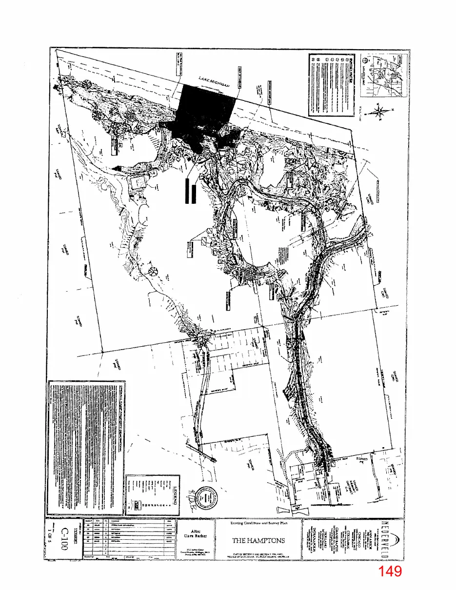
This page is a scanned image with no text layer. The PDF of these pages has it at full resolution.
Page 150
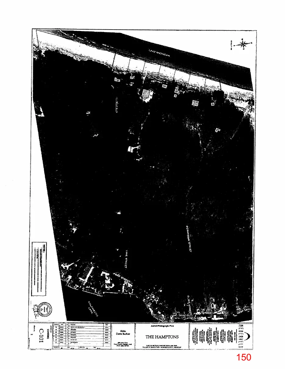
This page is a scanned image with no text layer. The PDF of these pages has it at full resolution.
Page 151
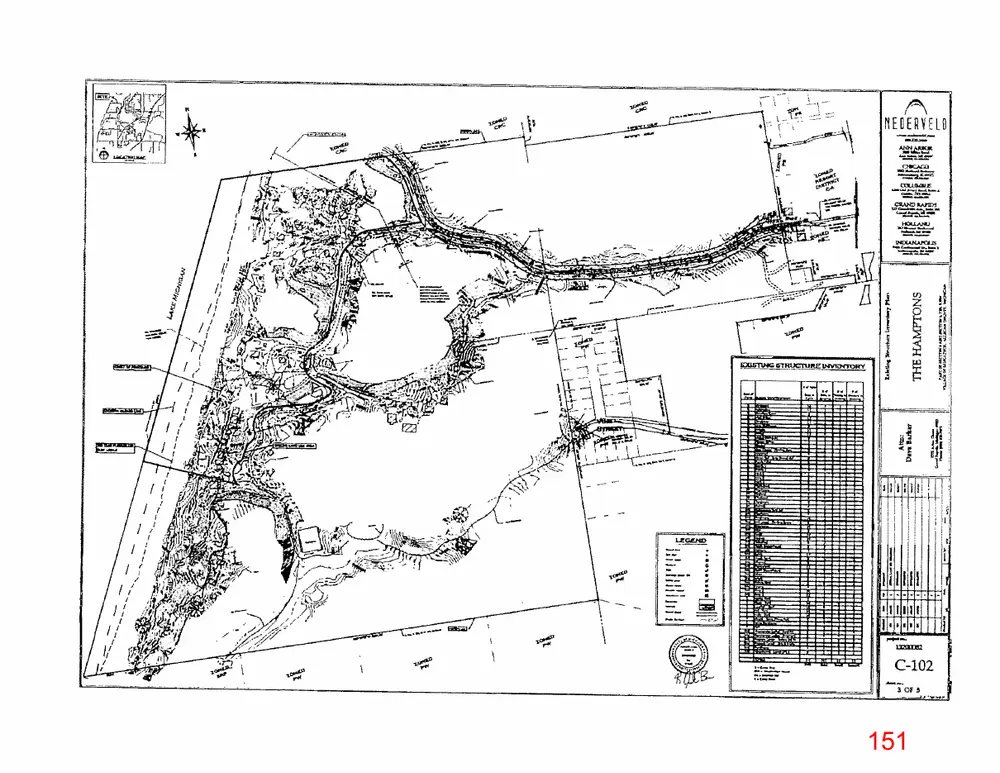
Text of page 151
NECERVEL9 AIN 1111...r aralsK CIIIPCAC43 COLIFICSIE fasaaa CAAND ItArDI HOLLSAU
14.1••••4.... NESANAPCIUS amm C*19...d“
, fd-
M..... —1=1
ciricjt?
•• • -7-",••••1•6 ma••••••••••• • 111•.,7,1••••••••• Malan ••••••••••••• al --=,..1••••• • MMMMM 1•• me, •• •• ••••••••••••• 61111 ,r... -,111•••••••• IMIU•••••• •••4111• IMF ..... me 110--11•11111•••••••• ini••••••••••1 •••••••• • IN MA. mmmamma num .' MMMMM NORM MAP .7.7 • NOM 1••••• ••••• ormi •••• •-• M ••••••••••••••••• ••••• MMMMM ••••••• 111.01111.1.1•1.••• MMMMM .4110111111 NM. MN 1111 WBO.MI •••••••1 •••••••••••••••••• oicam-rr via•••••••••18.1 01..11• •••••••••••■••In 1111,1111 ••1•••• MiZia .111[MM IMMO .1.111111111•11 NI ••••• 10..•!--..... ••••••••••••••••• 1•=0,- ... -,•••••• • on•••••••••• alre ,,,111•11•••••••••••••••• in•no••••••••• •••••• 0, z7. -••••••••••••• •Ir •••••••••••••••••• laillimsinum mom .1..m% MM 1•,111 . —..NNENIIIii./••••••••••••••••• l•-•• , .111.1.111•1= iMilln/Mann WriAl IM/ .110.1/1= ••••••••••• • o• 115.T• mil•Mo4w••••••In ND MB OM MMMMM WEI ...,• ••••••• •••••••• in=1, .-^3 •111 /•1•••••••••11•• 1•••••••11•11MI MOM -rm.^ awnt.•••••••• =MUNI MO MOB •••.•.7.1•••••••• wan • •••••• arIM•111•••••. Mau •M •••••• ••••••• en•R Mee •••••••••••• a. MMMM •••••• MMMMMM NM Ow= •I• MUM 1111:7.•.-7-,11•••••■••••••••••••• ••••••1•1.• 1.••••••1 ••••••••••• • MI6: Om /MD •
Page 152
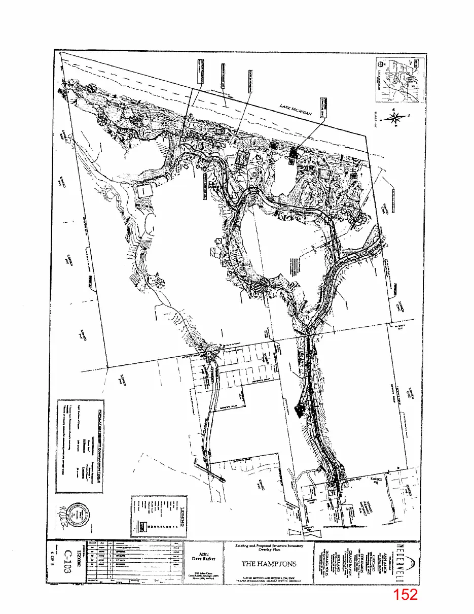
This page is a scanned image with no text layer. The PDF of these pages has it at full resolution.
Page 153
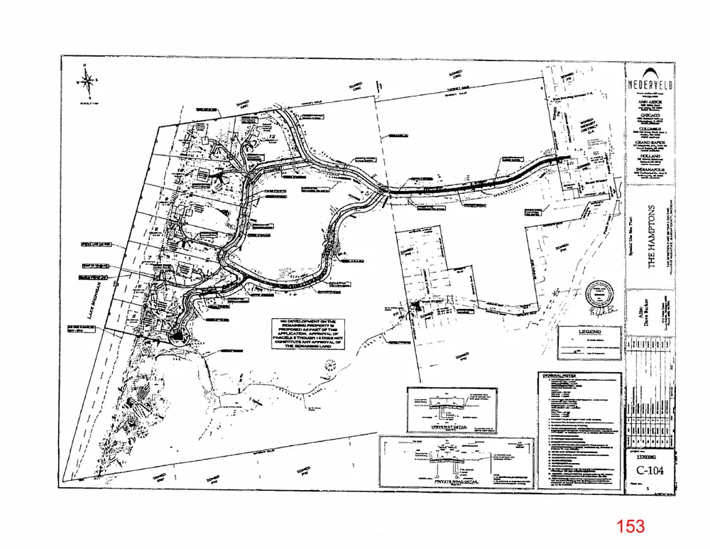
Text of page 153
DEVRILbPIONT ON 71111 1.101140111i1 POWWOW= AA row 00, APRICATE04. APINe011410I PAOKXLE • I Mtn CONIIIITI.1111AMT APPROVALOf XEMA/NUIGI LAND
LEGEND
ELMEASEMI.
•••••••••wommom......1.. "Z•1, :r.rxhiL
11•11•1•1104 1. ••••••••••••1111M.O. V••• NNW 0,../.0•Ir 11•••••il md••••11141110.
111% ••••••••••••• 0.1111•••••••......•
PNYATILMIlEsaks. .
Page 154
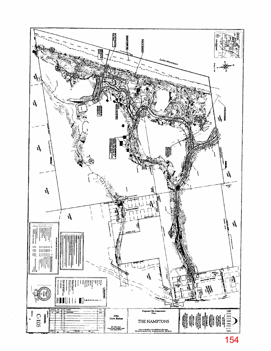
This page is a scanned image with no text layer. The PDF of these pages has it at full resolution.
Page 155
Text of page 155
CITY COUNCIL CITY OF SAUGATUCK ALLEGAN COUNTY. MICHIGAN At a special meeting of the City Council for the City of Saugatuck held at the City offices on June 10, 2015 at 4:00 P.111., Council Member Peterson offered the following resolution and moved its adoption, seconded by Council Member Trester: RESOLUTION NO. 150610-A A RESOLUTION APPROVING A PLANNED UNIT DEVELOPMENT FOR THE PROPERTY COMMONLY KNOWN AS 631 PERRYMAN (APPLICATION NO. 15-008), WITH CONDITIONS, ON THE RECOMMENDATION OF THE SAUGATUCK PLANNING COMMISSION WHEREAS, on or about March 11, 2013, the City of Saugatuck ("City") first received an application for special land use approval to develop twelve single family lots on a portion of the former Presbyterian Camp property commonly known as 631 Perry, man ("Property"); and WHEREAS, on December 3, 2013, following a series of public hearings and meetings at which the special land use application was discussed, the Planning Commission for the City of Saugatuck (the "Planning Commission") approved a resolution (Resolution No. 131203-A) pursuant to the City of Saugatuck Zoning Ordinance ("Zoning Ordinance") granting special land use and site plan approval for eight single-family lots on a portion of the Property; and WHEREAS, on or about November 1, 2014, the applicant Dune Ridge SA, LP ("Dune Ridge") filed a planned unit development ("PUD") application, as amended, on January 23, 2015 and March 12, 2015, for the development of an additional portion of the Property, which provided for the development of 14 single-family residential lots (of which one lot was included in the original eight lots approved in Planning Commission Resolution No. 131203-A), which if approved would allow for a total of 21 single-family residential lots on the entire Property; and WHEREAS, the City referred the PUD application to the Planning Commission, which held a public hearing on the application on April 16, 2015 and thereafter recommended approval of the PUD application and site plan to the City Council; and WHEREAS, on June 1, 2015, the City Council and Pluming Commission held public hearings related to the Property, at which they received further public comment regarding the PUD application; and WHEREAS, the City Council on June 1, 2015 tentatively approved the PUD application and site plan subject to several express conditions, and subject to review and approval of a resolution setting forth those conditions of approval;
Page 156
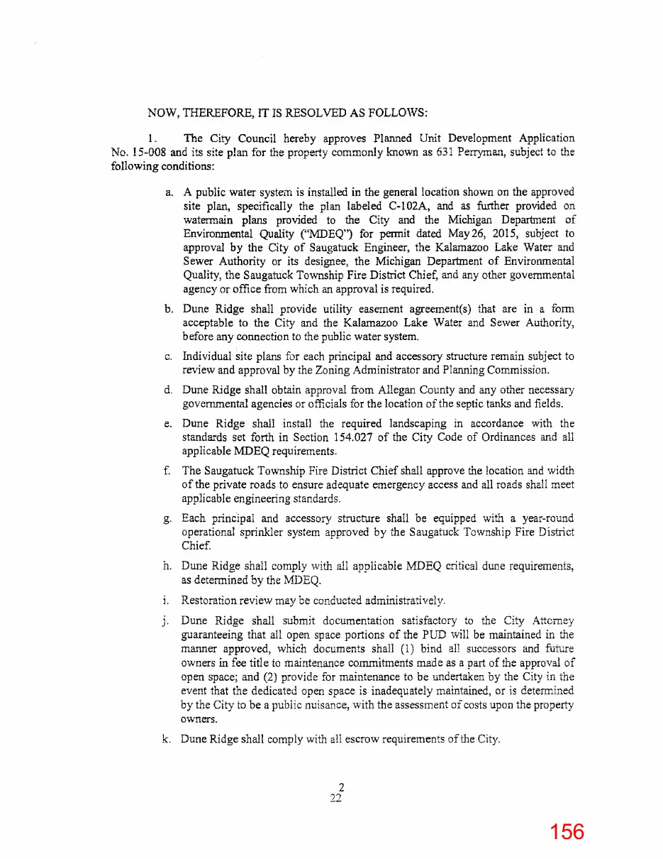
Text of page 156
NOW, THEREFORE, IT IS RESOLVED AS FOLLOWS: 1. The City Council hereby approves Planned Unit Development Application No. 15-008 and its site plan for the property commonly known as 631 Perryman, subject to the following conditions: a. A public water system is installed in the general location shown on the approved site plan, specifically the plan labeled C-102A, and as further provided on waterrnain plans provided to the City and the Michigan Department of Environmental Quality ("MDEQ") for permit dated May 26, 2015, subject to approval by the City of Saugatuck Engineer, the Kalamazoo Lake Water and Sewer Authority or its designee, the Michigan Department of Environmental Quality, the Saugatuck Township Fire District Chief, and any other governmental agency or office from which an approval is required. b. Dune Ridge shall provide utility easement agreement(s) that are in a form acceptable to the City and the Kalamazoo Lake Water and Sewer Authority, before any connection to the public water system. c. Individual site plans for each principal and accessory structure remain subject to review and approval by the Zoning Administrator and Planning Commission. d. Dune Ridge shall obtain approval from Allegan County and any other necessary governmental agencies or officials for the location of the septic tanks and fields. e. Dune Ridge shall install the required landscaping in accordance with the standards set forth in Section 154.027 of the City Code of Ordinances and all applicable MDEQ requirements. f. The Saugatuck Township Fire District Chief shall approve the location and width of the private roads to ensure adequate emergency access and all roads shall meet applicable engineering standards. g. Each principal and accessory structure shall be equipped with a year-round operational sprinkler system approved by the Saugatuck Township Fire District Chief. h. Dune Ridge shall comply with all applicable MDEQ critical dune requirements, as determined by the MDEQ. i. Restoration review may be conducted administratively. Dune Ridge shall submit documentation satisfactory to the City Attorney guaranteeing that all open space portions of the PUD will be maintained in the manner approved, which documents shall (1) bind all successors and future owners in fee title to maintenance commitments made as a part of the approval of open space; and (2) provide for maintenance to be undertaken by the City in the event that the dedicated open space is inadequately maintained, or is determined by the City to be a public nuisance, with the assessment of costs upon the property owners. k. Dune Ridge shall comply with all escrow requirements of the City_
2 22
Page 157
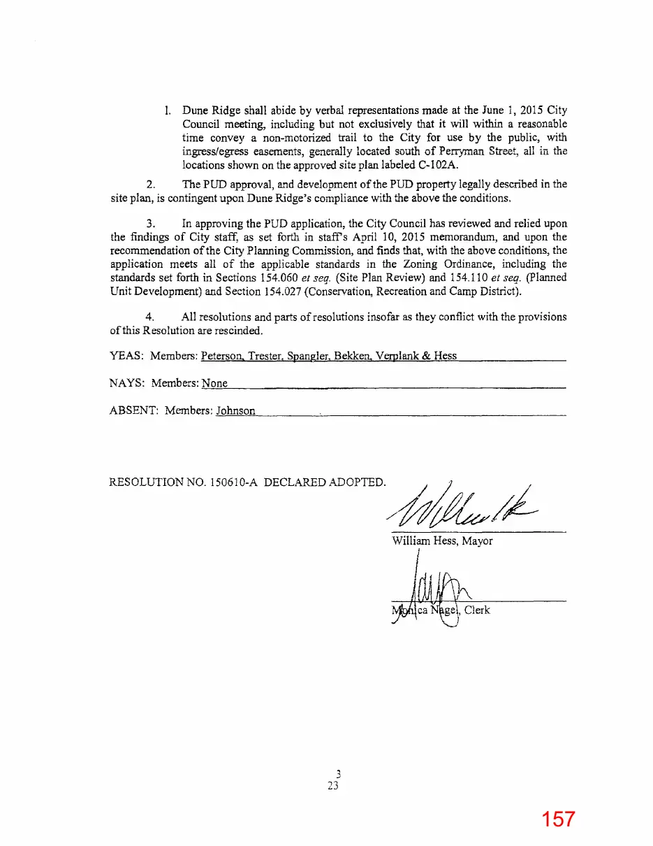
Text of page 157
1. Dune Ridge shall abide by verbal representations made at the June 1, 2015 City Council meeting, including but not exclusively that it will within a reasonable time convey a non-motorized trail to the City for use by the public, with ingLessiegress easements, generally located south of Perryman Street, all in the locations shown on the approved site plan labeled C-102A. The PUD approval, and development of the PUD property legally described in the 2. site plan, is contingent upon Dune Ridge's compliance with the above the conditions. 3. In approving the PUD application, the City Council has reviewed and relied upon the findings of City staff, as set forth in staff's April 10, 2015 memorandum, and upon the recommendation of the City Planning Commission, and finds that, with the above conditions, the application meets all of the applicable standards in the Zoning Ordinance, including the standards set forth in Sections 154.060 et seq. (Site Plan Review) and 154.110 et seq. (Planned Unit Development) and Section 154.027 (Conservation, Recreation and Camp District). All resolutions and parts of resolutions insofar as they conflict with the provisions 4. of this Resolution are rescinded. YEAS: Members: Peterson. Trester. S an ler Bekken. Verplank & Hess NAYS: Members: None ABSENT: Members: Johnson
RESOLUTION NO. 150610-A DECLARED ADOPTED.
William Hess, Mayor
3 23
Page 158
Text of page 158
CERTIFICATION I hereby certify that that the above is a true copy of the Resolution adopted by the City of Saugatuck City Council at the time, date, and place specified above pursuant to the required statutory procedures. Respectfull submitted,
By
4 24
Page 159
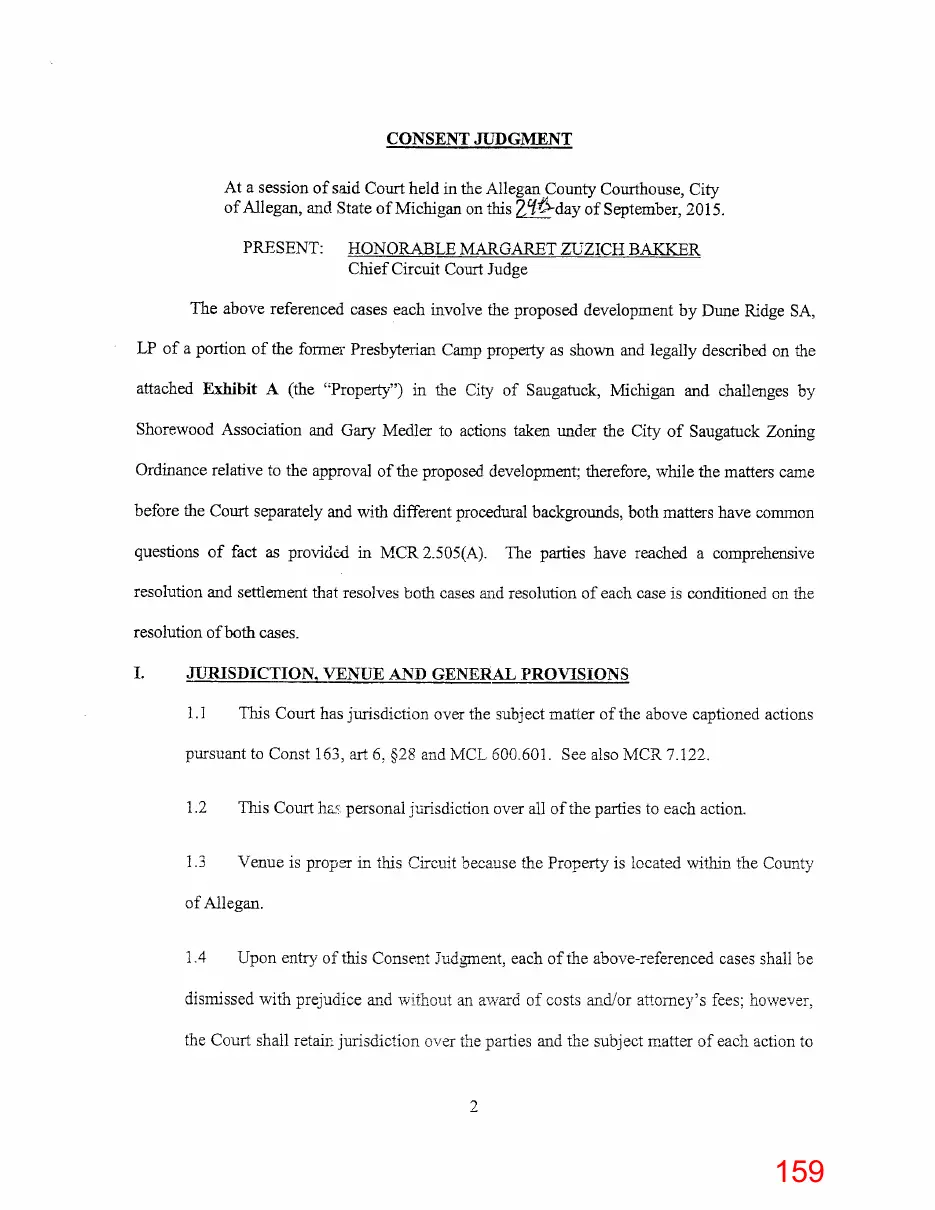
Text of page 159
CONSENT JUDGMENT At a session of said Court held in the Allegan County Courthouse, City of Allegan, and State of Michigan on this 216-day of September, 2015. PRESENT:
HONORABLE MARGARET ZUZICH BAKKER Chief Circuit Court Judge
The above referenced cases each involve the proposed development by Dune Ridge SA, LP of a portion of the former Presbyterian Camp property as shown and legally described on the attached Exhibit A (the "Property") in the City of Saugatuck, Michigan and challenges by Shorewood Association and Gary Medler to actions taken under the City of Saugatuck Zoning Ordinance relative to the approval of the proposed development: therefore, while the matters came before the Court separately and with different procedural backgrounds, both matters have common questions of fact as provided in MCR 2.505(A). The parties have reached a comprehensive resolution and settlement that resolves both cases and resolution of each case is conditioned on the resolution of both cases.
JURISDICTION, VENUE AND GENERAL PROVISIONS 1.1
This Court has jurisdiction over the subject matter of the above captioned actions
pursuant to Const 163, art 6, §28 and MCL. 600.601. See also MCR 7.122. 1.2
This Court ha.r personal jurisdiction over all of the parties to each action.
1.3
Venue is proper in this Circuit because the Property is located within the County
of Allegan. 1.4
Upon entry of this Consent Judgment, each of the above-referenced cases shall be
dismissed with prejudice and without an award of costs and/or attorney's fees; however, the Court shall retain jurisdiction over the parties and the subject matter of each action to
Page 160
Text of page 160
enforce this Consent Judgment and resolve disputes arising under the same, including those that may be necessary for its construction, execution and implementation. 1.5
Should a court of competent jurisdiction declare any provision of this Consent
Judgment to be unenforceable, the remaining provisions shall remain in effect. 1.6
This Consent Judgment shall bind and benefit not only the parties, but also their
assigns, successors in title, creditors, lessees and transferees in and to the Property, their respective properties or any part thereof, and this Order shall also bind and run with the lands involved. 1.7
A copy of this Consent Judgment may be recorded with the Allegan County
Register of Deeds. 1.8
The above-referenced cases are hereby consolidated into Case No. 13-52646-CZ
pursuant to MCR 2.505(A)(2). 1.9
To avoid the burden, expense and uncertainty of further litigation and appeals; after
consultation with their respective legal counsel and extensive negotiations, the parties have agreed to a comprehensive compromise and settlement of both cases to fully and finally resolve their disputes through this Consent Judgment. 1.10 The Court finds in reliance on the parties' stipulation that the terms and conditions of this Consent Judgment are fair, adequate and reasonable, consistent with the public interest, and adequately resolve the subject matter of this case.
Page 161
Text of page 161
1.11 Except as otherwise provided herein, this Consent Judgment is neither an admission nor denial of liability, fault or error with respect to any of the claims raised in the above captioned cases, or any issue addressed in this Judgment. 1.12 All parties represent and guarantee that they have the legal power and authority to execute and enter into this Consent Judgment. 1.13 This Consent Judgment is a comprehensive settlement and compromise, and fully adjudicates all of the claims, defenses, appeals and causes of action in this consolidated case, including those pleaded and which could have been pleaded and constitutes the final order of the Court. II.
PARTIES AND BACKGROUND 2.1
Appellant Shorewood Association ("Shorewood") is a Summer Resort
Association created under 1897 PA 230 and is the title holder to Lots 1-74 inclusive, all streets, the athletic area and the beach park and all land comprising the Plat of Shorewood located in the City of Saugatuck, County of Allegan and shares common a boundary with the Property, as described below, of approximately 700 feet. 2.2
Appellee and Defendant City of Saugatuck ("City") is an incorporated Home Rule
City in the State of Michigan. 2.3
Intervening Appellee and Defendant Dune Ridge SA, LP ("Dune Ridge") is the
owner of the Property that is the subject of this action. 2.4
Plaintiff G-ary Medler ("I`viedler") is an individual who owns three lots and resides
at 461 Vine Street, Saugatuck, County of Allegan. Michigan 49453, title to which is held by the Gary E. Medler Trust, dated June 13, 2007, and which is located on three lots, lots 4
Page 162
Text of page 162
5, 6 and A on the attached Exhibit B, and as legally described on the attached Exhibit B (the "Medler Property"). The Medler Property shares a common boundary with the Property and Medler alleges the Medler Property would be negatively impacted by any development of the Property adjacent to the Medler Property, including but not limited to, the improvement and extension of Vine Street into the Property, the installation and extension of public sanitary sewer and public water from the end of Vine Street into the Property. 2.5
On or about March 11, 2013, the City first received an application for special land
use permit to develop twelve single family lots on a portion of the Property; the application was subsequently amended to reduce the number of proposed lots from twelve to eight. 2.6
In November 2013, Plaintiff Medler sought an appeal to the City's Zoning Board
of Appeals seeking to challenge the City Zoning Administrator's determination that the proposed use was allowed under the City Zoning Ordinance with special land use approval ("Appeal"). 2.7
The City refused to process Medler's Appeal, claiming it was untimely,
prompting Medler to sue the City in this action and prompting Dune Ridge to intervene as a Defendant. 2.8
Defendants and Intervening Defendants dispute Medler's Appeal and contend the
actions taken by the City of Saugatuck Planning Commission ("Planning Commission") and the City's determination that Medler's Appeal was untimely were consistent with the City's Zoning Ordinance.
Page 163
Text of page 163
2.9
On December 3, 2013, following a series of public hearings and meetings at
which the special land use application was discussed, the Planning Commission approved a resolution pursuant to the Zoning Ordinance granting special land use and site plan approval for a portion of the Property (Resolution No. 131203-A, as amended, referred to herein as the "SLU Resolution"), which allowed for the development of eight singlefamily residential lots on the area described in the SLU Resolution as the "Residential Property", as shown and legally described on Exhibit C, and left the remainder of the Property as "Undeveloped Property" (the terms "Residential Property" and "Undeveloped Property" shall have the same meaning in this Consent Judgment as they are given in the SLU Resolution). 2.10 Appellant Shorewood filed a Claim of Appeal with this Court challenging the SLU Resolution as, among other things, not authorized by law (the "Claim of Appeal"). 2.11 Appellee City and Intervening Appellee Thme Ridge dispute Appellant's Claim of Appeal and contend the action taken by the Planning Commission was valid and consistent with law. 2.12 By Order dated December 2, 2014, this Court dismissed Appellant's Claim of Appeal and Appellant has filed a motion to reconsider. The December 2, 2014 order shall be hereby vacated to the extent it could be considered inconsistent with the relief granted in this Consent Judgment. 2.13 On or about November 1, 2014, Dune Ridge filed a planned unit development ("PUD") application, as amended on January 23, 2015 and March 12, 2015, for the development of an additional portion of approximately 30.1 acres of the Undeveloped
Page 164
Text of page 164
Property (the "PUD Property"), which provided for the development of 14 single-family residential lots (of which one lot was included in the original eight lots approved in the SLU Resolution) as shown and legally described on the attached Exhibit D. 2.14 The Residential Property and the PUD Property are both part of the Property to be developed into a total of 21 single-family residential lots. 2.15 The City referred the PUD application to the City's Planning Commission, which held a public hearing on April 16, 2015 and recommended approval of the PUD application and site plan to the City Council. 2.16 On June 1, 2015, the City held a joint City Council and Planning Commission public hearing, following which (1) the Planning Commission adopted a resolution approving a request by Dune Ridge to change the location of the public water system servicing the Property, and reaffirming that the individual units in the Residential Property remain subject to site plan review by the Planning Commission (i.e., denying Dime Ridge's request for administrative review of individual site plans); and (2) the City Council tentatively adopted the PUD application, subject to final approval by the Council of a resolution or consent judgment setting forth the Council's findings and the conditions of the approval. 2.17 On June 10, 2015, the City Council approved a resolution pursuant to the Zoning Ordinance approving the PUD Application and Site Plan for the PUD Property (Resolution 150610-A, referred to herein as the "PUD Resolution"), Exhibit E.
Page 165
Text of page 165
III.
RESOLUTION 3.1
Notwithstanding any other provision of the City ordinances to the contrary, and
consistent with City Ordinance No. 150309-1, which authorizes the use of a septic disposal system in critical dune area such as the Property, no public sanitary sewer system will be installed or constructed on any part of the Property including the Residential Property, the PUD Property and the Undeveloped Property. 3.2
Public water will be provided for by means of a connection to the municipal water
system at Frederick (Maple) Street and Vine Street, extending north on Frederick Street, with a connecting water line off Frederick Street, west through the Property and connecting to the municipal water system at Perryman Street and the main entrance to the Property, all as depicted on the Site Plan attached as Exhibit D, and as further provided on watermain plans provided to the City and the Michigan Department of Environmental Quality ("MDEQ") for City permit dated May 26, 2015, subject to approval by the City of Saugatuck Engineer, the Kalamazoo Lake Water and Sewer Authority or its designee, the Michigan Department of Environmental Quality, the Saugatuck Township Fire District Chief, and any other governmental agency or office from which an approval is required. 3.3
Installation of the public water system described in Section 3.2 shall be
accomplished by means of directional drilling and boring in all open spaces and along Perryman Street pursuant to an engineered approved plan approved by the City, which shall include staging areas and a reclamation plan for bentonite slurry, acceptable to the City. All bore pits and property disturbance shall be restored to pre-installation conditions.
Page 166
Text of page 166
3.4
Dune Ridge shall neither request nor pursue an extension of Vine Street or any other
road or pathway which would connect Vine Street to the Property. 3.5
Nothing in this Consent Judgment prohibits Medler from seeking vacation of any
unimproved portion of Vine Street through the usual means; however, this Consent Judgment does not vacate any portion of Vine Street. Dune Ridge has no objection, and shall not object, to any request by Medler to the City to vacate and convey to Medler the unimproved portion of Vine Street. 3.6
Except as provided in the SLU Resolution, as amended by the Planning
Commission on March 19, 2015 and June 1, 2015, and as provided in the PUD Resolution as approved and effective June 10, 2015, Dune Ridge shall not propose and the City shall not approve any additional residential imits or other development on the Property or any amendment to the Site Plans attached as Exhibits C and D, except for de minimus, nonmaterial changes that do not alter the character of the unimproved portions of the Property. 3.7
The PUD, with accompanying site plan, was approved as meeting all of the
applicable standards in the Zoning Ordinance, and may be constructed according to an approved, executable engineering plan, subject to the conditions set forth in Resolution No. 150610-A, attached as Exhibit E, which was adopted by the City of Saugatuck City Council, on the recommendation of the City of Saugatuck Planning Commission, on June 10, 2015, and the parties waive the right to challenge or appeal the PUD approval.
Page 167

Text of page 167
3.8
The SLU Resolution and PUD Resolution and all other resolutions, determinations,
decisions and conditions by the City or its departments or designees, and any other governmental body, agency or official related in any manner to the Property, which were issued or adopted prior to the date of this Consent Judgment remain binding and in effect and are enforceable by the appropriate entity to the extent the resolutions, determinations, decisions and conditions are not inconsistent with this Consent Judgment. This is a final decision and closes the cases.
IT IS SO ORDERED. MARGARET 7LPTC1-4 3AKKER Margaret Zuzich Bakker Chief Circuit Court Judge
31iP i).
CLIER S
BY SIGNING BELOW EACH PARTY CONSENTS TO THE FORM, SUBSTANCE AND ENTRY OF THIS CONSENT JUDGMENT:
By:
By: Cry al L. Morg (P68837) BLO M SLUGGETT _AORGAN, PC Attorneys for the City of Saugatuck and Saugatuck Defendants
Joel G. Bouwens (P26306) CUNNINGHAM DALMAN, PC Attorneys for Shorewood Association
By:
By: Aaron M. Phelps (P64790) VARINium LLP Attorneys for Dune Ridge SA, LP
Lee T. Silver (P36905) Douglas W. Van Essen (P33169) SILVER & VAN ESSEN, PC Attorneys for Medler
Page 168
Text of page 168
3.8
The SLU Resolution and PUB Resolution and all other resolutions, determinations,
decisions and conditions by the City or its departments or designees, and any other governmental body, agency or official related in any manner to the Property, which were issued or adopted prior to the date of this Consent Judgment remain binding and in effect and are enforceable by the appropriate entity to the extent the resolutions, determinations, decisions and conditions are not inconsistent with this Consent Judgment. This is a final decision and closes the cases.
IT IS SO ORDERED.
Margaret Zuzich Bakker Chief Circuit Court Judge
BY SIGNING BELOW EACH PARTY CONSENTS TO THE FORM, SUBSTANCE AND ENTRY OF THIS CONSENT JUDGMENT:
By:
By: el G. Bouwens (P26306) UNN1NGHA tvi DALMAN; PC Attorneys for Shorewood Association
Crystal L. Morgan (P68837) BLOOM SLUGGETT MORGAN, PC Attorneys for the City of Saugatuck and Saugatuck Defendants
By:
By: Lee T. Silver (P36905) Douglas W. Van Essen (P33169) SILVER & VAN ESSEN, PC Attorneys for Medler
Aaron M. Phelps (P64790) VARNUM LLP Attorneys for Dune Ridge SA, LP
Page 169
Text of page 169
3.8
The SLU Resolution and PUD Resolution and all other resolutions, determinations,
decisions and conditions by the City or its departments or designees, and any other governmental body, agency or official related in any manner to the Property, which were issued or adopted prior to the date of this Consent Judgment remain binding and in effect and are enforceable by the appropriate entity to the extent the resolutions, determinations, decisions and conditions are not inconsistent with this Consent Judgment. This is a final decision and closes the cases.
IT IS SO ORDERED.
Margaret Zu7.ich Bakker Chief Circuit Court Judge
BY SIGNING BELOW EACH PARTY CONSENTS TO THE FORM, SUBSTANCE AND ENTRY OF THIS CONSENT JUDGMENT:
By:
By: Joel G. Bouwens (P26306) CUNNINGHAM D_A_LMAN, PC Attorneys for Shorewood Association
Crystal L. Morgan (P68837) BLOOM SLUGGETT MORGAN, PC Attorneys for the City of Sauotuck and Saui ik Defendants
Lee T. Silver (P36905) Douglas W. Van Essen (P33169) SILVER & VAN ESSEN, PC Attorneys for Medler
Aaron M. Phelps (P64790 VARNUM LLP Attorneys for Dune Ridge SA,
By:
Page 170
Text of page 170
SHORE WOOD ASSOCIATION
CITY OF SAUGATUCK AND SAUGATUCK DEFENDANTS
By:
By: William Hess Its: Mayor Its:
DUNE RIDGE SA, LP By:
By: Gary Medler Its:
9625873_1.DOCX
Page 171
Text of page 171
SHORE WOOD ASSOCIATION
CITY OF SAUGATUCK SAUGATUCK DEFE
By:
By: William Hess
Its: Mayor Its:
DUNE RIDGE SA, LP By:
By: Gary Medler Its:
9625873_1.DOCX
Page 172
Text of page 172
SHORE WOOD ASSOCIATION
CITY OF SAUGATUCK AND SAUGATUCK DEFENDANTS
By:
By: William Hess Its: Mayor Its:
DUNE RIDGE SA, LP By:
By:
9625873_1 .DOCX
Page 173
Text of page 173
SHORE WOOD ASSOCIATION
CITY OF SAUGATUCK AND SAUGATUCK DEFENDANTS
By:
By: William Hess Its: Mayor Its:
DUNE RIDGE SA, LP, a Delaware limited partnership By: Dune Ridge A GP, LLC, a Michi 'lity company, er G r
By: Gary Medler
By: Paulus C. Heule, its Manager
9625873_1.DOCX
Page 174
Text of page 174
EXHIBIT A Legal Description of the Property
Part of Section 8 and Section 9, Town 3 North, Range 16 West, City of Saugatuck, Allegan County, Michigan, described as: Beginning at the East 1/4 comer of said Section 8; thence SOO°13153"W 1292.28 feet along the East line of the Southeast 1/4 of said Section 8; thence N89°32'30"W 2424.03 feet along the South line of the North 1/2 of the Southeast fractional 1/4 of said Section 8 to Reference Point "A"; thence continuing N89°32'30"W 20 feet, more or less, to the Water's edge of Lake Michigan; thence Northeasterly 2440 feet, more or less, along said Water's edge of Lake Michigan to the intersection of said water's edge of Lake Michigan and a line bearing N89°07'21"W from Reference Point "B" ( said Reference Point "B" being located N24°36'39"E 2438.62 feet from Reference Point "A"); thence S89°07'21"E 20 feet, more or less, to Reference Point "B"; thence continuing S89°07'21"E 760.89 feet along the South line of the North 400.00 feet of the South 1/2 of the Northeast fractional 1/4 of said Section 8; thence Southeasterly 204.36 feet along a 305.17 feet radius curve to the right, the chord of which bears S25°06'59"E 200.55 feet; thence S10°26'40"E 61.70 feet; thence Southeasterly 91.60 feet along a 890.86 feet radius curve to the left, the chord of which bears S14°08'20"E 91.56 feet; thence Southeasterly 82.11 feet along a 200.00 feet radius curve to the left, the chord of which bears S36°01`39"E 81.53 feet; thence Southeasterly 257.44 feet along a 530.00 feet radius curve to the left, the chord of which bears S66°02'11"E 254.92 feet; thence Southeasterly 156.94 feet along a 260.00 feet radius curve to the right, the chord of which bears S50°48'12"E 154.57 feet; thence Southeasterly 172.35 feet along a 311.00 feet radius curve to the left, the chord of which bears S56°52'59"E 170.16 feet; thence S77°55`01"E 60.84 feet; thence 582°11'13"E 183.00 feet; thence Southeasterly 202.55 feet along a 1050.00 feet radius curve to the left, the chord of which bears S85°57'06"E 202.24 feet; thence N89°45'36"E 303.06 feet; thence Northeasterly 173.15 feet along a 525.00 feet radius curve to the left, the chord of which bears N76°21'49"E 172.37 feet; thence S61°44`25"E 98.34 feet; thence SOO°52'42"E 119.95 feet; thence S40°49'12"E 85.65 feet; thence S89°59'45"W 1066.62 feet along the East-West 1/4 line of said Section 9 to the East 1/4 corner of said Section 8 and the Point of Beginning.
Page 175
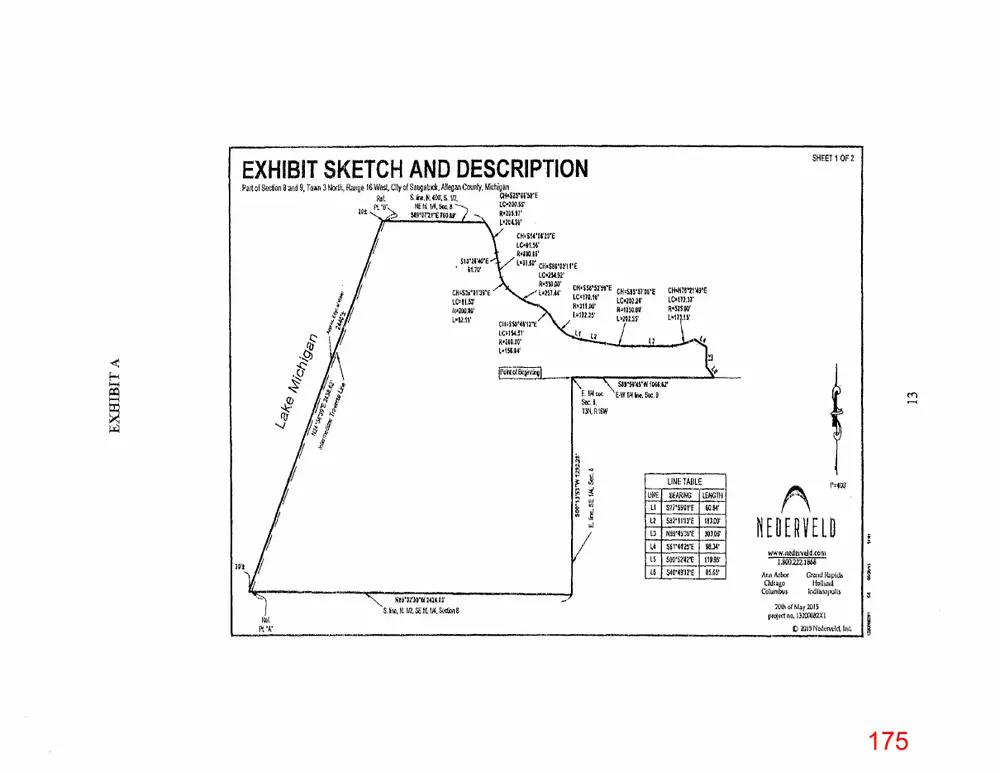
Text of page 175
SHEET 1 OF 2
EXHIBIT SKETCH AND DESCRIPTION Part of Section 8 and 9, Town 3 Rath, Range 16 West, City of SaUgatock, Megan County, Michigan 1:43.52511'591 S. liut N. 400', S. I12, Ret 10•200.55' NE 81 I/4, Ser, 8 PL 208 Re3D5.17' 9419°01711760,19' L.294.34' CHe8141120E tC,.91.55' R.450.16' S1025'40E
CH:Sei'8119"E LCeB1,57 11.200.90' L82,11'
closo.4413I LC.154.57' R.260.66' L.155.94'
C11•585'0VIPE LS.254,92' R4550.00' 611455.5'52'591 4151715'E Le25744 L0.170,15' LC*29224' Reel I AO' 6.1659.08 1.022.35' Lu292.55'
Slte81711`21491 LC.I72.32' Re525.00' Le11 88
[Foil of Br $59°591,5°911054,42' E-W 1/41ise, Sec. 9
LINE TABLE l
l' 400'
LINE 8EA6M LEHG111 LI
52755'61E
5821113E
I 83.00'
Nt19.4636"E
503,06'
L4
56114 25.6
98.34'
SO0'52'42'E
119.95'
640'4612'E
85,65'
NEDEPVELEJ www.netlerveld.com 1.800.222.1868 Ann Arbor Chicago Columbus
Grand Rapids It ollund Indlanupolls
N591219'W 242443' 70111 ot Aia y 2015 proiert no, 132C00RX I
S. be, N, VI, SE It 114, Sorlion 8
E) 2015 Ilalerveld, Inn
Pt 'A' immliellaBINO•M
Page 176
Text of page 176
EXHIBIT B
461 VINE STREET LEGAL DESCRIPTION Property consists of 3 Lots. Adjacent Lots 5 and 6 in Upham's Addition plus a Landlocked Lot adjacent to Lots 5 and 6 to the south. Lot 6 and the Landlocked Lot are adjacent to the Camp property to the west. Title is held as Gary E. Medler Trust, Gary E. Medler, Trustee. Lots 5 and 6 Tax ID No. 57-850-003-00; Landlocked Lot Tax ID No. 57-009-074-10
Page 177
Text of page 177
EXHIBIT B
Sar43%7"E S 'rD u‘ 'EEM W1.4414 34.€ s78-3.31.ve 2521' 24. 2•244.51
I4:7;15::3WE
GRAVEL PARKING
513 11MaliEn
51.1 COR. LOT
SOUTH LINE OF U.Pi-lAr1'5 ADDITION
, M-4417' N09'.4416'E N26'30'E 5.E CDR, LOT 5 a 111311
55,1'4352'H
404 BROAZWAY SOUTH HAVEN, MICHIGAN 49090 OFFICE: (269) 637-1107 toLX; J.2eS) 637-1907-
MITCHELL & MORSE LAND SURVEYING A DIVI51-014 Of MITCHELl. SURVEYS, INC.
C. MORSE Y EDWARD PROFESSIONAL
FRED NIUNDINGER
Cz.ICHT DATE
7-27-2007
OWE. Of Scipor, N THE
-114
July No.
03-992
'OWE. CK
SW I/4 SECTION SAUGATUCK (CITY) Trip. 1= SO' 323 SCALE SooK
;sr
sKtrri
3N
ALLEGAN pAzE
Otsr:_ CK
Orsc.PY
15W CO:, M3LNIC4N
REVislow
SURVEYOR KEITH F. )(LUTING
PROFESSIONAL 5LIRVETOr. %EORGE J.. D4 paorEss) SuRvcr
Page 178
Text of page 178
EXHIBIT C Legal Description of the Residential Property Part of Section 8, Town 3 North, Range 16 West, Village of Saugatuck, Allegan County, Michigan, described as: Commencing at the East 1/4 corner of said Section 8; thence N89°59'16"W 1191.51 feet along the East-West 1/4 line of said Section 8 to the Point of Beginning; thence Southerly 75.38 feet along a 93.00 feet radius curve to the left, the chord of which bears 530°10'35"E 73.33 feet; thence 553°23'43"E 73.10 feet; thence Southerly 40.06 feet along a 20.00 feet radius curve to right, the chord of which bears 503°59'28W 33.69 feet; thence Southerly 61.95 feet along a 277.00 feet radius curve to the right, the chord of which bears S67°47'04"W 61.82 feet; thence Southerly 56.98 feet along a 162.00 feet radius curve to the right, the chord of which bears 584°16'04"W 56.69 feet; thence N85°39'21"W 166.97 feet; thence Southerly 159A9 feet along a 88.00 feet radius curve to the left, the chord of which bears 542°25'20"W 138.54 feet; thence Southerly 43.85 feet along a 37.00 feet radius curve to the right, the chord of which bears 524°27'16"W 41.33 feet; thence Southerly 71.29 feet along a 118.00 feet radius curve to the left, the chord of which bears S41°06'03 "W 70.21 feet; thence 523047'34"W 20.81 feet; thence Southerly 23.34 feet along a 30.00 feet radius curve to the right, the chord of which bears 546°04'50"W 22.76 feet; thence Southerly 128.54 along a 70.00 feet radius curve to the left, the chord of which bears 515°45'39"W 111.23 feet; thence N67°09'05"W 436.00 feet to Reference Point "A"; thence continuing N67°09'05"W 20 feet more or less to the water's edge of Lake Michigan; thence Northeasterly 1385 feet more or less along said water's edge of Lake Michigan to the intersection of said water's edge of Lake Michigan and a line bearing N89°07'21"W from Reference Point "B" along the South line of the North 400 feet of the South 1/2 of the Northeast fractional 1/4 of said Section 8 (said Reference Point "B" being located N24°32'49"E 1392.13 feet from Reference Point "A"); thence 589°07'21"E 20 feet more or less along said South line to Reference Point "B"; thence continuing 589°07'21"E 760.89 feet along said South line; thence Southerly 204.36 feet along a 305.17 feet radius curve right, the chord of which bears S25°06'59"E 200.55 feet; thence 510°26'40"E 61.70 feet; thence Southerly 91.60 feet along a 890.86 feet radius curve to the left, the chord of which bears 514'08'20"E 91.56 feet; thence 589°55'29"W 255.69 feet; thence Southerly 76.08 feet along a 108.00 feet radius curve to the left, the chord of which bears 569°44'42"Vvr 74.51 feet; thence 548°45'34"W 83.10 feet; thence Southerly 67.05 feet along a 133.00 feet radius curve to the left the chord of which bears 527°31'19"W 66.34 feet; thence 515°20'44"W 128.03 feet; thence 520°11'38"W 183.86 feet; thence Southerly 55.55 feet along a 77.00 feet radius curve to the right, the chord of which bears 540°51'41"W 54.35 feet; thence 561°31'45"W 65.70 feet; thence Southerly 111.16 feet along a 93.00 feet radius curve to the left, the chord of which bears 527°17'09"W 104.70 feet to the Point of Beginning. Contains 23 acres more or less. Subject to easements, restrictions, and rights of way of record.
Page 179
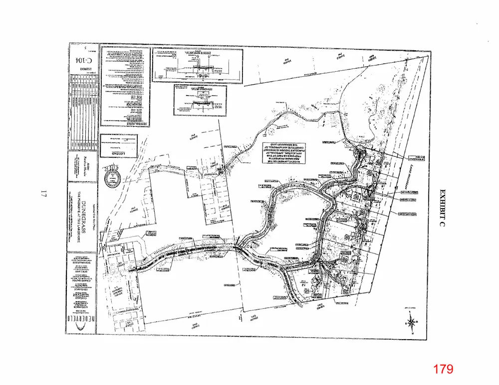
Text of page 179
maasna.
7.7;17.71:11:::
VOTI-D ------'
110007.CI
1.57• 4.1..1.11.11a
^27:73.;:g :774.41.7S.L17.1t.7 77=7
TRre0
47 ,7.rg • ." : :7741 7:47:
21100 10004Ntlo
6901202075 01411 0+100V14211 31.11 4101Y000It3if ANY 3171L11.111403 140100 VI lion0111ion! aened J/01VA04,400 1.01114041dolV PM 4010W kV 030.0.1000
el Alkri dOkhl
4L14 14114.10110114 oIl
... _ 00.0'047,
—r'rrA-. coennpvtl
Ni0811949
001100010 /01,01,1
Page 180
Text of page 180
EXHIBIT D Legal Description of the PUD Property
Part of Section 8, Town 3 North, Range 16 West, City of Saugatuck, Allegan County, Michigan, described as: Commencing at the East 1/4 comer of said Section 8; thence SOO°13'53"W 1292.28 feet along the East line of the Southeast 1/4 of said Section 8; thence N89°32'30"W 1564.14 feet along the South line of the North 1/2 of the Southeast fractional 1/4 of said Section 8 to the Point of Beginning; thence continuing N89°32'30"W 859.89 feet along said South line to Reference Point "C"; thence continuing N89°32.1 30"W 20 feet more or less to the water's edge of Lake Michigan; thence Northeasterly 1250 feet more or less along said water's edge of Lake Michigan to the intersection of said water's edge of Lake Michigan and a line bearing N67°07'35''W from Reference Point "A" (said Reference Point "A" being located N24°41'45"E 1246.85 feet from Reference Point "C"); thence S67°07'3511E 20 feet more or less to Reference Point "A"; thence continuing S67°07'35"E 525.76 feet; thence Northeasterly 7.24 feet along a 110.00 feet radius curve to the left, the chord of which bears N21°20'49"E 7.24 feet; thence 1\119°28'22"E 57.92 feet; thence Northeasterly 38.82 feet along a 126.00 feet radius curve to the left, the chord of which bears NI0°38'50"E 38.66 feet; thence Northeasterly 3.11 feet along a 15.00 feet radius curve TO the right, the chord of which bears N07'43'36"E 3,11 feet; thence N13°37'54"E 19.60 feet; thence Northeasterly 6.30 feet along a 22.00 feet radius curve to the right, the chord of which bears N86°08'13"E 6.28 feet; thence S85°39'21"E 166.97 feet; thence Northeasterly 80.20 feet along a 228.00 feet radius curve to the left, the chord of which bears N84°16'04"E 79.78 feet; thence Northeasterly 76.71 feet along a 343.00 feet radius curve to the left, the chord of which bears N67°47'04"E 76.55 feet; thence Northeasterly 29.76 feet along a 86.00 feet radius curve to the left, the chord of which bears N51°27'50"E 29.61 feet; thence Northeasterly 44.53 feet along a 30,00 feet radius curve to the right, the chord of which bears N84°04'38"E 40.56 feet; thence S53°23'43E 7.48 feet; thence Southeasterly 412.83 feet along a 458.00 feet radius curve to the left, the chord of which bears S79°13'05E 399.00 feet; thence N74°57'34"E 61,85 feet; thence Northeasterly 8.80 feet along a 113.00 feet radius curve to the left, the chord of which bears N72.°43144"E 8.80 feet; thence SOO°17'18"W 329.17 feet; thence S34°49'50"W 503.49 feet; thence S87°32'36''W 421.10 feet; thence S48°41'40"W 429.00 feet to the Point of Beginning. Contains 33 acres more or less. Subject to easements, restrictions and rights of way of record,
Page 181
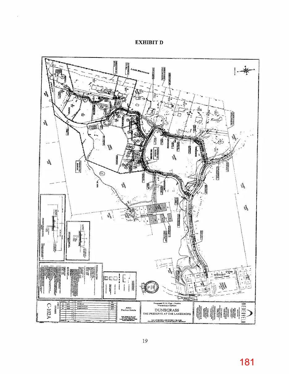
Text of page 181
EXHIBIT D
'Aro
' tit Iti i 4
IP
tt,.. i:;
; 1111411111111 41 II iptlif4Hil I {111 11111 iiiiiiiHNIIWil ' I igdq:V.1 Me p!7,; •iI , ET ,,Ii, liqvIrl! . 0, v !Iiiii
,I ill li I ' i‘ WI i .1
thi:h; 14011
int' I ihq I il I
,___ _ 1 — C -L: L--1 o 1 I 11 i 1 I 11
.1"rura
71mr, • T.1. c
Wa,arr.-.0.pEon
.A.ttru Paulus H.
DUNTEGRA.SS THE PRE-SF—RVE. AT THE LA.Ir—SHORE jpsnme Anor0,
afr,
go 0. 7 Et ,P